Description
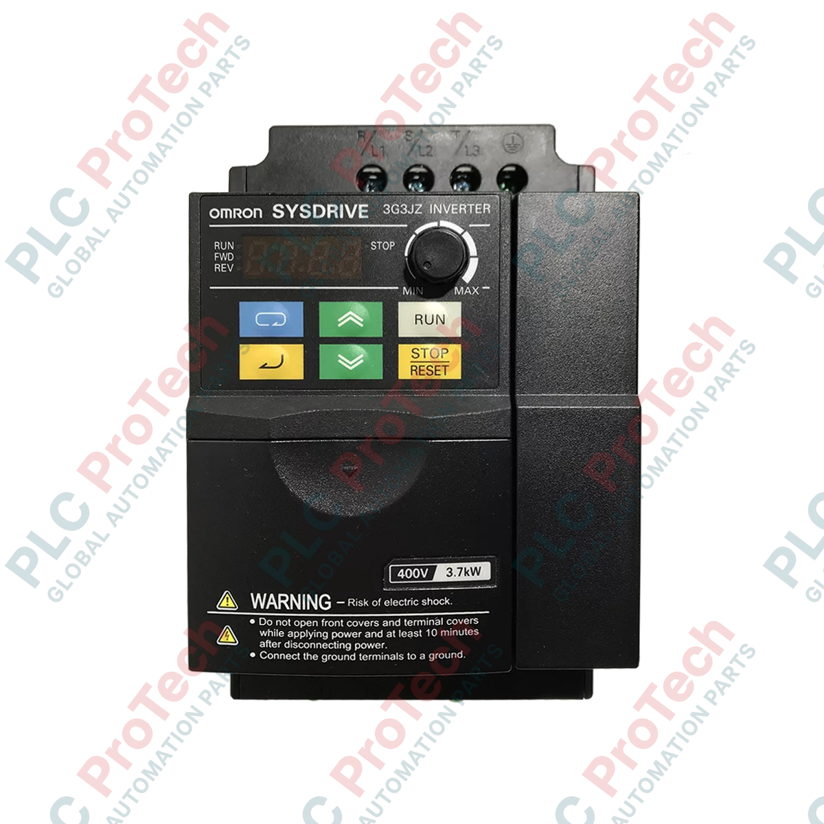
Providing precise motor speed control within compact industrial architectures, the Omron 3G3JZ-A2015 variable frequency drive is engineered for three-phase 200V applications demanding high operational efficiency. This SYSDRIVE 3G3JZ series inverter supports up to 1.5 kW motor capacities, delivering reliable performance and dynamic torque response. Built with an IP20-rated protective enclosure, it is designed for secure panel integration or closed wall-mount configurations, making it a rugged choice for demanding machine control panels.
Key Features
-
Precise Output Rating: Fully optimized to drive 3-phase AC motors up to 1.5 kW capacity.
-
Resilient Panel Enclosure: Rated IP20 minimum, suitable for space-saving side-by-side mounting.
-
Efficient Thermal Management: Engineered layout for efficient heat dissipation inside closed control panels.
-
User-Friendly Interface: Simplifies on-site calibration, parameter setting, and fault diagnostics.
Applications
-
Conveyor and Material Handling: Provides smooth starting torque and precise velocity control.
-
Pumping and HVAC Systems: Regulates fluid and air flow velocities to conserve energy.
-
Packaging Machinery: Handles rapid stop/start cycles with predictable deceleration ramps.
-
Automated Production Lines: Seamlessly integrates with master PLC architectures via discrete and analog control loops.
Technical Specifications
| Parameter |
Specification Value |
| Manufacturer |
Omron |
| Model Code |
3G3JZ-A2015 |
| Product Series |
SYSDRIVE 3G3JZ |
| Input Voltage Class |
3-Phase AC 200V Level (200 to 240 VAC) |
| Max Applicable Motor Capacity |
1.5 kW (2.0 HP) |
| Enclosure Rating |
IP20 (Panel Mounting/Closed Wall Mounting) |
| Cooling Method |
Forced air cooling / Fan cooled |
| Shipping Weight (Calculated) |
3.0 kg |
Connections and Interfaces
| Terminal Symbol |
Description and Terminal Function |
| R/L1, S/L2, T/L3 |
Main circuit AC power supply input terminals (3-phase 200 to 240 VAC) |
| U/T1, V/T2, W/T3 |
Inverter output terminals connected directly to the 3-phase AC motor |
| +1, +2 / B1, B2 |
DC reactor connection and external dynamic braking resistor terminals |
| Ground (PE) |
Safety earth ground terminal (must be grounded securely to prevent ESD/EMI issues) |
Empirical Engineering Insights
Alternative Models & Compatibility
The legacy 3G3JZ series can often be upgraded to newer Omron MX2 (3G3MX2) or RX series variable frequency drives. When migrating, verify physical dimensional differences, terminal positioning, and Modbus control register addresses, as legacy 3G3JZ parameters will require manual mapping to the newer CX-Drive configurations.
Application Pitfalls & Engineering Notes
Avoid installing the unit in areas of high humidity or where conductive metallic dust is present. Ensure a minimum clearance of 120 mm above and below the drive housing when installing inside a closed electrical panel to allow natural convection, even when forced-air cooling fans are operational. Running the drive close to its thermal thresholds significantly shortens the operational lifespan of the internal DC bus capacitors.
Commissioning & Wiring Tips
To eliminate electromagnetic interference (EMI) issues with nearby low-voltage analog control wiring (such as 4-20mA or 0-10V PLC output loops), always run power input/output cables and signal cables in separate conduits. Additionally, use shielded, symmetrical motor cabling and ground the shield at both the inverter PE terminal and the motor frame.
Installation Guidelines
CRITICAL WARNING: Hazardous voltages remain present within the drive's internal capacitors even after disconnecting the AC input supply. Disconnect all electrical power sources and wait at least 10 minutes for the charge to bleed off. Confirm zero voltage across the DC bus terminals using a trusted, calibrated digital voltmeter before touching any wiring connections or electronic components.
1
Mount the inverter vertically to a flat, metallic panel backplate to assist with grounding and heat dissipation.
2
Terminate input power conductors to terminals R/L1, S/L2, and T/L3. Connect motor lines to U/T1, V/T2, and W/T3.
3
Configure control signals (source/sink parameters) based on your system design requirements before energizing the drive.