Description
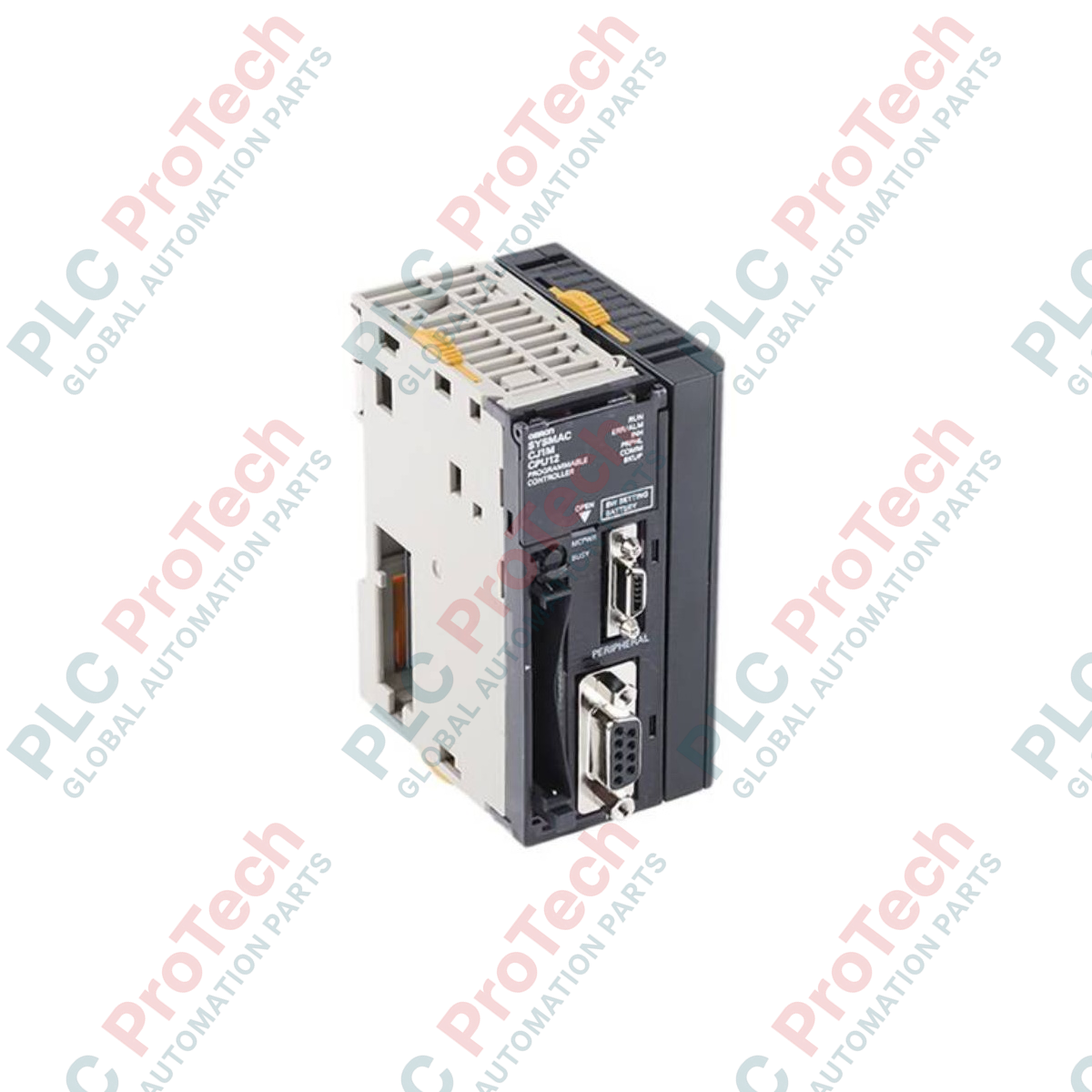
Executing logical control in localized machinery setups, the Omron CJ1M-CPU12 CPU unit delivers high-speed, compact processing power for automated systems. This unit manages up to 320 local I/O points and coordinates up to 10 directly connected modules without the need for expansion racks. Engineered for precision and space-constrained enclosures, it features a logical instruction execution speed of 100 nanoseconds and integrates built-in serial and peripheral communications to streamline fieldbus networking and configuration.
Key Features
-
Direct Rack-Mounted Control: Supports up to 10 CJ-series expansion units directly on the CPU rack.
-
Dual Integrated Communication Ports: Features one dedicated peripheral port and one RS-232C port for simultaneous HMI, programming tool, or third-party serial interface connections.
-
Optimized Memory Configuration: Features 10 Ksteps of program capacity and 32 Kwords of DM (Data Memory) space.
-
Compact Flash Card Slot: Supports external memory card operations for backup data, logging, and parameter transfers.
-
Interrupt and Subroutine Capabilities: Handles up to 1024 subroutines/jumps and 2 scheduled interrupts for time-critical automation routines.
Applications
- Packaging machinery control and sequencing
- Small-scale material handling systems and conveyors
- Auxiliary and secondary control cabinets in wastewater and automotive plants
- Distributed machinery sub-assembly integration
Technical Specifications
| Specification Parameter |
Value / Rating |
| Manufacturer |
Omron |
| Model Number |
CJ1M-CPU12 |
| Product Series |
CJ-series CJ1M CPU Units |
| I/O Capacity |
320 Points max. |
| Expansion Rack Support |
Not Supported (Local CPU Rack ONLY) |
| Max. Connectable Units |
10 Units |
| Program Capacity |
10 Ksteps |
| Data Memory Capacity |
32 Kwords (DM area only; no EM area) |
| LD Instruction Time |
100 ns (0.1 us) |
| MOV Instruction Time |
0.3 us |
| System Overhead Time |
0.5 ms |
| Built-in Ports |
1 Peripheral Port, 1 RS-232C Port |
| Subroutines / Jumps |
1,024 |
| Scheduled Interrupts |
2 |
| Option Card Support |
CompactFlash Card (external slot) |
| Shipping Weight (Calculated) |
2.0 kg (including commercial protective packaging) |
Connections and Interfaces
| Connector / Port |
Functional Assignment / Configuration |
| Peripheral Port |
Connects to CJ-series programming console or CS1W-CN226/CN626 cables for CX-Programmer connectivity. |
| RS-232C Port |
9-pin D-sub interface used for Host Link (Sysmac Way), NT Link, No-protocol serial, or Modbus-RTU master/slave communications. |
| CF Card Slot |
Accepts industrial CompactFlash memory cards for automated file transfers, program restoration, and system parameter logging. |
Empirical Engineering Insights
Alternative Models & Compatibility
The CJ1M-CPU12 bridges the gap between the entry-level CJ1M-CPU11 (160 I/O) and the CJ1M-CPU13 (640 I/O). If upgrading from legacy CQM1 systems, note that the physical footprint, instruction address mappings, and communication cables are distinct. Additionally, unlike the larger CJ1M-CPU2x series, this processor lacks built-in pulse I/O or positioning outputs on the CPU board, meaning motion tasks require separate CJ1W-NC position control modules.
Application Pitfalls & Engineering Notes
Because this CPU does not support expansion racks, users are strictly capped at 10 slots on the main CPU rack. When configuring the system, perform a comprehensive current consumption analysis. High-density output modules combined with network units can exceed the current rating of the power supply unit. In such setups, upgrade the power supply to the CJ1W-PA202 (AC) or CJ1W-PD022 (DC) to prevent system drops or communications faults.
Commissioning & Wiring Tips
Verify the physical status of the hardware configuration DIP switches behind the front cover flap prior to commissioning. Switch 5 determines the communication protocol of the built-in RS-232C port. Setting Switch 5 to ON forces toolbus default programming protocols, ignoring settings defined in CX-Programmer's PLC Setup. Conversely, setting Switch 5 to OFF activates the customized serial parameters written to system memory.
Installation Guidelines
CRITICAL WARNING: Ensure all primary and auxiliary AC/DC supply voltages are completely de-energized before mounting, removing, or wiring modules. Failure to disconnect system power can cause terminal degradation, destroy internal memory components, and cause communication card damage.
1
DIN-Rail Mounting:
Hook the upper claw of the CJ1M-CPU12 unit onto the top of the DIN rail, then press the unit firmly downward until the bottom yellow locking track clip clicks into place.
2
Module Coupling:
Engage the integrated connectors on the sides of adjacent modules. Slide the yellow lock levers on both the top and bottom of the CJ1M unit forward until they click, locking the CPU and adjacent modules together.
3
Ground Connection:
Ensure the Functional Ground (FG) terminal on the adjacent power supply module is connected to a dedicated, low-impedance ground point (under 100 ohms) using AWG 14 or larger wire to minimize electrostatic interference.