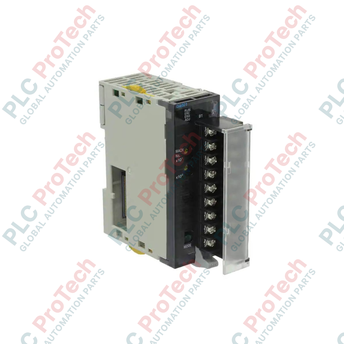
Description
Regulating analog actuators and control loops within Sysmac PLC architectures is the primary functional role of the Omron CJ1W-DA021. This CJ-series Special I/O Unit provides two high-resolution analog output channels, supporting standard industrial current and voltage ranges. Built with internal photocoupler isolation between the controller backplane and the external interface, this module prevents field electrical noise from corrupting core logic operations. The physical connection is established through an 18-point detachable terminal block with M3 screws, facilitating rapid wiring, commissioning, and simplified hot-swap unit replacement during field maintenance.
Key Features
-
Dual-Channel Output: Supports two independent analog outputs configurable for voltage or current loops.
-
Flexible Signal Ranges: Compatible with standard industry spans including 1 to 5 V, 0 to 5 V, 0 to 10 V, -10 to 10 V, and 4 to 20 mA.
-
High Resolution: Operates at a maximum conversion resolution of up to 40,000 for precise variable control.
-
Photocoupler Isolation: Secure isolation barrier between the internal PLC controller backplane and external output circuitry.
-
Maintenance-Friendly Terminal Block: Detachable 18-point block with M3 screws allows replacement without disconnecting field wiring.
Applications
-
Variable Speed Drive Regulation: Direct frequency and speed commanding for industrial inverters and VFDs.
-
Proportional Valve Control: Modulating flow rates, pneumatic pressures, and hydraulic positions in process loops.
-
HVAC Damper Actuation: Positioning air dampers and control valves based on real-time environmental demands.
-
External Chart Recording: Routing physical process variables to analog instrumentation, displays, or recording units.
Technical Specifications
| Parameter |
Value / Specification |
| Manufacturer |
Omron |
| Model Code |
CJ1W-DA021 |
| Product Type |
CJ-series Special I/O Unit (Analog Output Module) |
| Number of Outputs |
2 channels |
| Output Ranges (Voltage) |
1 to 5 V, 0 to 5 V, 0 to 10 V, -10 to 10 V |
| Output Ranges (Current) |
4 to 20 mA |
| Max Resolution |
1/40,000 (Set data: 16-bit binary) |
| Output Impedance (Voltage) |
0.5 Ohm max. |
| Max Output Current (Voltage) |
12 mA (for 1 point) |
| Max Permissible Load Resistance |
600 Ohm (for current output) |
| Backplane Current Consumption |
5 VDC, 120 mA max. |
| External Power Supply Requirements |
24 VDC +10% -15%, 140 mA max. (Inrush: 20 A max., 1 ms min. pulse) |
| Isolation Method |
Photocoupler isolation between I/O and controller backplane (No isolation between channels) |
| External Connections |
18-point detachable terminal block (M3 screws) |
| Unit Weight |
0.15 kg |
| Shipping Weight |
1.50 kg (including secure export packaging) |
Connections and Interfaces
| Terminal Assignment |
Signal Name |
Functional Circuit Assignment |
| V OUT 1 |
Voltage Output 1 |
Positive voltage output connection for Channel 1 |
| I OUT 1 |
Current Output 1 |
Positive current output connection for Channel 1 |
| COM 1 |
Output Common 1 |
Common return terminal for Channel 1 |
| V OUT 2 |
Voltage Output 2 |
Positive voltage output connection for Channel 2 |
| I OUT 2 |
Current Output 2 |
Positive current output connection for Channel 2 |
| COM 2 |
Output Common 2 |
Common return terminal for Channel 2 |
| 24 VDC |
External Power Supply (+) |
Positive supply terminal for external 24 VDC input |
| 0 VDC |
External Power Supply (-) |
Negative/Ground reference for external 24 VDC input |
Empirical Engineering Insights
Alternative Models & Compatibility
The CJ1W-DA021 serves as a direct drop-in replacement for older CJ1W-DA021 revision versions. When planning retrofits from older Sysmac platforms (such as the C200H series), direct logic mapping is required because of backplane addressing variations. Ensure your CJ1G, CJ1H, or CJ2H CPU unit has been allocated corresponding DM and CIO Area channels using CX-Programmer or Sysmac Studio software to match the unit's rotary physical address switches.
Application Pitfalls & Engineering Notes
A key layout constraint is that no isolation exists between output channels 1 and 2. Both channels share a common internal ground point. If you connect this module to two field devices that are separately grounded at different physical points, ground loops can form, causing signal drift or module damage. To prevent this, always route outputs to devices with internally isolated inputs, or add physical external loop isolators between the module and any non-isolated field targets.
Commissioning & Wiring Tips
Ensure that the external 24 VDC power supply is fully active before or simultaneously with the PLC CPU backplane startup. If the external 24 VDC drops below the -15% tolerance limit (20.4 VDC), the module's orange status indicator will trip, and an I/O verification error will register at the processor level. Always use shielded, twisted-pair cables for analog routing and ground the shield only at the PLC chassis ground terminal to avoid ambient RF noise infiltration.
Installation Guidelines
CRITICAL WARNING
Disconnect all electrical power to the PLC rack and field-side circuits before physically attaching or removing this Special I/O Unit. Failure to completely de-energize the assembly can destroy internal components or cause erratic PLC CPU behavior.
1
Set the unit number rotary dials on the front panel of the CJ1W-DA021 to the desired address (0 to 95) prior to mounting. Avoid duplicating unit numbers across the PLC backplane.
2
Align the upper and lower track hooks of the module with the adjacent rack unit, slide the unit securely into position, and engage the locking slide clamps on the top and bottom of the CJ-series rack.
3
Wire the 18-point detachable terminal block with crimped M3 terminals, ensuring positive 24 VDC external supply connections are completed before powering on the system.