Description
Facilitating high-speed industrial Ethernet communications within modular control architectures, the Omron CJ1W-EIP21 functions as a CPU Bus Unit designed to interface PLC controllers directly with industrial EtherNet/IP networks. This unit enables both high-speed tag data links (implicit messaging) for real-time I/O control and message communications (explicit messaging) for explicit data exchange. Integrating seamlessly onto either local CPU racks or expansion racks, it bridges logical plant-floor control layers with supervisory SCADA, MES, or enterprise database environments without requiring dedicated external gateways.
Features
- Support for implicit (cyclic) tag data links and explicit CIP message communications.
- Flexible installation across NJ-series systems, CJ-series platforms, and CP1H micro-controllers.
- Dynamic IP address configuration options including BOOTP and rotary node address switches.
- Simultaneous multi-protocol handling including EtherNet/IP, FTP client/server, and FINS TCP/IP communications.
- Comprehensive diagnostics via built-in LED indicators and system status variables in the PLC memory map.
Applications
- Distributed I/O integration and control across multi-rack PLC topologies.
- Peer-to-peer processor interlocking in high-speed manufacturing assembly lines.
- SCADA, HMI, and MES system interfacing for real-time performance tracking and data acquisition.
- Motion and variable frequency drive orchestration via Ethernet-based control loops.
Technical Specifications
| Manufacturer |
Omron Industrial Automation |
| Model Number |
CJ1W-EIP21 |
| Unit Classification |
CJ-series CPU Bus Unit |
| Supported Platforms |
NJ-series, CJ-series, CP1H-series PLCs |
| Physical Mounting Locations |
CPU Rack, Expansion Rack |
| Maximum Units per System |
NJ System: 4 max | CJ/NSJ System: 8 max | CP1H System: 2 max |
| Media Access Control (MAC) |
CSMA/CD |
| Modulation Method |
Baseband |
| Transmission Topology |
Star formation (via switching hubs) |
| Baud Rate |
100 Mbit/s (100Base-TX) |
| Maximum Segment Distance |
100 meters (node to network switch/hub) |
| Internal Current Consumption |
410 mA maximum at 5 V DC |
| Dimensions (H x W x D) |
90 mm x 31 mm x 65 mm |
| Unit Weight |
0.094 kg (94 g) |
| Shipping Weight (Calculated) |
1.5 kg |
Connections and Interfaces
| Interface Component |
Description / Pin Assignment |
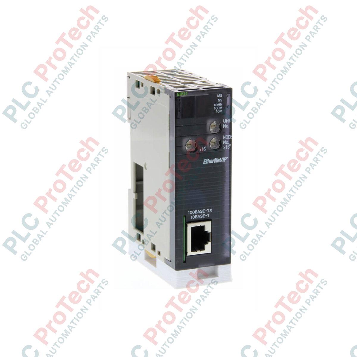
| RJ45 Connector |
Standard 8-pin modular connector for 100Base-TX Ethernet cable (Category 5/5e shielded twisted pair recommended). |
| Rotary Switches |
Two hex decimal rotary switches (x16 and x1) located on the front panel to configure the hardware node IP address suffix. |
| LED Indicators |
RUN (Green), ERC (Red), ERH (Red), MS (Green/Red), NS (Green/Red), LNK/ACT (Yellow). |
Empirical Engineering Insights
Based on industrial commissioning logs, the configuration and management of the CJ1W-EIP21 require precise adherence to network bandwidth constraints and configuration rules.
Alternative Models & Compatibility
The CJ1W-EIP21 can directly replace older CJ1W-ETN21 Ethernet modules in legacy network topographies, though configuration steps differ. When migrating to an NJ-series controller platform, the unit's maximum allowable instances drop from 8 units (CJ-series limit) to 4 units due to increased backplane bandwidth demands. Ensure the unit's firmware matches the Sysmac Studio or CX-Programmer library version to avoid catalog mismatch faults during upload.
Application Pitfalls & Engineering Notes
A common real-world failure mode occurs when Tag Data Link (implicit messaging) connections saturate the unit's maximum packet processing rate (PPS). Keep track of your packet limits using the Network Configurator tool. If the cumulative packet-per-second limit is exceeded, cyclic communications may time out, throwing an 'ERH' (EtherNet/IP Unit Error) status. To alleviate this, adjust the Requested Packet Interval (RPI) configurations upward for non-critical monitoring nodes.
Commissioning & Wiring Tips
To minimize high-frequency electrostatic interference on plant-floor environments, you must use double-shielded STP Cat 5e (or better) cabling. Clamp the shield securely to the rack's functional ground bar. When utilizing the rotary switches on the front bezel to set the IP address, note that the default hardware setting reads the node address as part of the Class C IP scheme (e.g., 192.168.250.X). If custom routing or non-standard subnets are required, set the rotary switches to '00' to enable software-configured IP parameters via CX-Programmer.
Installation Guidelines
CRITICAL WARNING: Hazardous voltage levels can cause severe electrical shock or equipment damage. Prior to installing, removing, or wiring any CPU Bus Unit, completely de-energize the entire rack power supply. Wait at least 5 minutes to allow residual bus charge to fully bleed off before physically decoupling any module.
1
Align the top hook of the CJ1W-EIP21 module into the mounting slot of the CJ/NJ-series backplane.
2
Pivot the unit downward until the bottom connector snaps securely into the bus socket on the backplane.
3
Tighten the upper and lower mounting screws to secure the chassis. Ensure they are tightened to the recommended torque of 0.4 N-m.
4
Insert the RJ45 Ethernet patch cord until the locking tab clicks cleanly into place. Ensure proper strain relief is applied to prevent physical pull on the port.