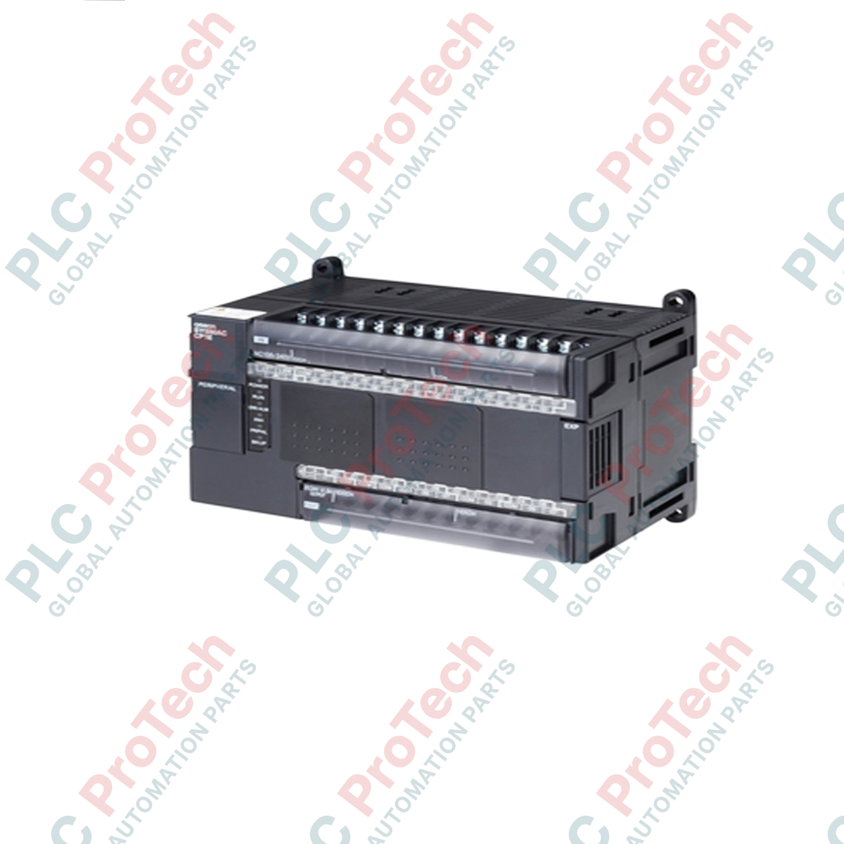
Description
Executing core automation and sequential tasks in industrial environments, the Omron CP1E-N60SDR-A serves as an integrated, space-saving programmable controller designed for compact machinery. This application-ready unit integrates 36 digital inputs and 24 relay outputs directly onto its main chassis, eliminating the need for immediate expansion modules in standard configurations. Operating on a universal 100 to 240 VAC power supply, this controller manages complex logic with an 8k-step program capacity and an 8k-word data memory, making it a reliable solution for cost-sensitive automation tasks.
Key Features
-
High-Density Local I/O: Outfitted with 36 inputs (24 VDC) and 24 relay outputs to minimize panel space requirements.
-
Wide Power Range: Operates reliably on alternating current lines from 100 to 240 VAC at 50/60 Hz.
-
Ample Memory Capacity: Features 8k-step program execution capacity paired with 8k words of data memory for extensive parameter storage.
-
Auxiliary Output Supply: Generates a clean 24 VDC auxiliary output at 0.30 A to power local field sensors directly.
-
Low Power Losses: Optimizes thermal efficiency with a low current draw of 0.21 A at 5 VDC and 0.13 A at 24 VDC.
Industrial Applications
- Conveyor sequencing and sorting line automation.
- Packaging machinery, horizontal wrappers, and labeling systems.
- Water treatment pumping cycles and localized HVAC damper controls.
- Material handling systems and small-scale gantry controls.
Technical Specifications
| Parameter |
Specification Value |
| Manufacturer |
Omron |
| Model Number |
CP1E-N60SDR-A |
| Series |
CP1E |
| Power Supply Voltage |
100 to 240 VAC, 50/60 Hz |
| Total Onboard I/O |
60 Points |
| Digital Inputs |
36 Inputs (24 VDC) |
| Digital Outputs |
24 Outputs (Relay) |
| Output Switching Type |
Relay |
| Program Memory |
8k Steps |
| Data Memory |
8k Words |
| External Aux Power Supply |
24 VDC @ 0.30 A |
| Current Consumption (5 VDC) |
0.21 A |
| Current Consumption (24 VDC) |
0.13 A |
| Standards & Certifications |
CE Compliant |
| Shipping Weight |
3 kg |
Connections and Interfaces
| Terminal Label |
Functional Assignment |
| L1, L2/N |
100 to 240 VAC Primary Main Power Input |
| Protective Earth (PE) |
Chassis Ground connection for noise immunity |
| + / - (Auxiliary) |
24 VDC output terminal for external sensor loop excitation |
| 00.00 to 02.11 |
Direct 24 VDC Digital Inputs (Grouped Commons) |
| 10.00 to 12.07 |
Normally-Open (NO) Relay Output Terminals |
| USB Port |
Built-in peripheral port for standard programming via CX-Programmer |
Empirical Engineering Insights
Alternative Models & Compatibility
The N-type (CP1E-N60SDR-A) features a built-in USB port and support for standard serial communication boards. If replacing a standard CP1E-E unit, confirm your configuration setup, as standard E-type logic programs that utilize specific instructions or serial interface add-ons will require system verification in CX-Programmer before execution.
Application Pitfalls & Engineering Notes
When utilizing the built-in auxiliary 24 VDC power supply, avoid overloading past the 0.30 A limits. Running the auxiliary supply near its limits while operating under elevated ambient panel temperatures can trigger thermal shutdown mechanisms or lead to early component failure.
Commissioning & Wiring Tips
Ensure that inductive output loads, such as solenoids or contactor coils, have parallel suppression elements (freewheeling diodes for DC systems and RC snubbers for AC lines). Failing to suppress inductive kickback will wear out the onboard mechanical relay contacts prematurely and generate noise that can interrupt the PLC central processor.
Installation Guidelines
CRITICAL WARNING
Isolate and lock out all high-voltage electrical power sources feeding the system before mounting, wiring, or servicing the unit. Verify the total lack of voltage across input terminals. Failure to perform lock-out/tag-out procedures can cause severe electrical shock, physical injury, or total destruction of hardware components.
1
Mount the controller onto a standard 35 mm DIN rail in a horizontal orientation, allowing a minimum of 50 mm clearance above and below the device for natural air convection currents.
2
Connect the mains power line (100 to 240 VAC) directly to the designated AC power terminals using standard 1.25 mm square AWG wire, and tie the PE terminal directly to your central safety grounding point.
3
Route your input wiring (24 VDC logic) and high-voltage output wiring through separate, segregated wire trays to avoid electromagnetic induction noise on signal cables.