Description
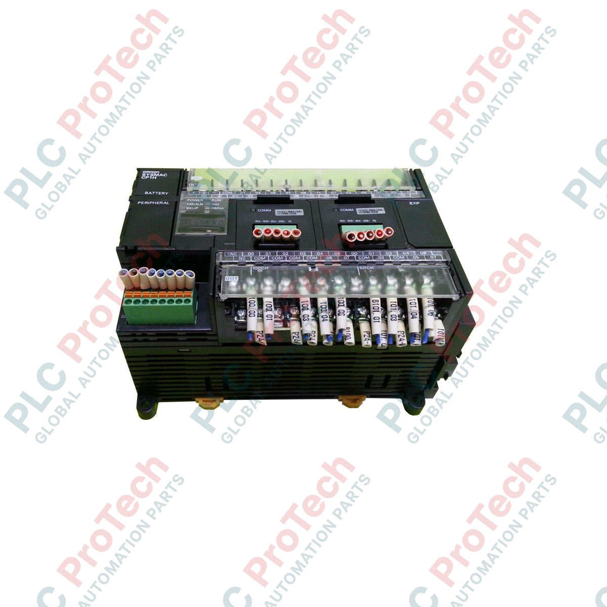
Engineered for multi-axis positioning and integrated process control, the Omron CP1H-XA40DT1-D serves as a high-density, all-in-one programmable logic controller (PLC) optimized for sophisticated factory automation systems. This compact controller integrates 4-axis high-speed pulse outputs, versatile built-in analog input/output circuits, and a robust 40-point digital I/O system within a single, space-saving form factor. Operating on a 24 VDC power supply, it features sourcing transistor outputs that align perfectly with modern safety standards and industrial field devices.
The integrated analog section offers high-resolution signal conversion, rendering external analog cards unnecessary for basic closed-loop control applications. Combined with the performance of a modular PLC, this micro-controller easily handles complex mathematical calculations and high-speed motion operations, making it a reliable foundation for modular machine designs.
Features
-
High-Speed Positioning: Four-axis pulse outputs reaching up to 100 kHz permit precise control of servo and stepper drive systems without auxiliary modules.
-
Onboard Analog Integration: Equipped with 4 analog inputs and 2 analog outputs with a resolution of 1/12,000 for accurate processing of current and voltage field signals.
-
Sourcing Transistor Outputs: Features 16 sourcing (T1) transistor outputs designed to switch external loads safely up to 24 VDC.
-
Flexible Expansion Path: Supports direct connection of up to 7 CP1W expansion units, and up to two CJ-series specialized modules using a CJ unit adapter.
-
Advanced Communication Options: Dual board slots accept optional RS-232C, RS-422A/485, or Ethernet option boards for seamless SCADA and HMI integration.
Applications
- Multi-axis pick-and-place packaging systems
- Precision semiconductor handling and alignment stages
- Local pump, flow, and chemical dosing stations
- Automatic sorting and high-speed material handling conveyors
Technical Specifications
| Parameter |
Specification Value |
| Manufacturer |
Omron |
| Model Number |
CP1H-XA40DT1-D |
| Power Supply Voltage |
24 VDC (Operating range: 20.4 to 26.4 VDC) |
| Digital Input Points |
24 Inputs (24 VDC, response time selectable from 0 to 32 ms) |
| Digital Output Points |
16 Outputs (Sourcing Transistor, 24 VDC, 0.3 A per point) |
| Built-in Analog Inputs |
4 channels (0-10V, 1-5V, 0-20mA, 4-20mA; Resolution: 1/12,000) |
| Built-in Analog Outputs |
2 channels (0-10V, 1-5V, 0-20mA, 4-20mA; Resolution: 1/12,000) |
| Pulse Outputs |
4 axes, 100 kHz maximum frequency (sourcing outputs) |
| High-Speed Counters |
4 axes, Phase-difference inputs: 50 kHz, Single-phase inputs: 100 kHz |
| Program Capacity |
20k steps (EEPROM backup, battery-backed RAM) |
| Data Memory Capacity |
32k words |
| Operating Temperature |
0 to 55 degC (ambient operating environment) |
| Shipping Weight (Calculated) |
1.10 kg |
| Package Dimensions (Calculated) |
160 mm x 120 mm x 100 mm |
Connections and Interfaces
| Terminal Group |
Function Assignment |
| Power Terminals |
24 VDC (+ / -) input connection, Functional Ground (FG) terminal, Protective Earth (PE) terminal. |
| Digital Input Blocks |
Terminals CIO 0.00 to CIO 0.11 and CIO 1.00 to CIO 1.11. Includes high-speed counter inputs. |
| Digital Output Blocks |
Terminals CIO 100.00 to CIO 100.07 and CIO 101.00 to CIO 101.07. Sourcing transistor configuration (V+ common). |
| Analog I/O Terminals |
Dedicated voltage/current inputs (AD0 to AD3), outputs (DA0 to DA1), and AG (analog ground) reference points. |
Empirical Engineering Insights
Alternative Models & Compatibility
When migrating from older models or replacing a sinking unit (such as the CP1H-XA40DT-D), note that the CP1H-XA40DT1-D features sourcing outputs (T1 suffix). This requires a fundamental rewiring of external loads from 0 VDC commons to 24 VDC commons. PLC programs compiled in CX-Programmer can be transferred directly between CP1H configurations, though physical output common polarities must be carefully validated prior to power-up.
Application Pitfalls & Engineering Notes
During dense cabinet installations with high ambient temperatures, running all four 100 kHz pulse output axes simultaneously can generate localized heat. Maintain the specified clearance of 20 mm above and below the unit to allow natural air convection. Additionally, the maximum current per output point is 0.3 A. Ensure high-current inductive loads (such as heavy-duty contactors) are switched via intermediate interposing relays to prevent thermal degradation of the sourcing transistor array.
Commissioning & Wiring Tips
Noise on analog channels can significantly degrade feedback precision. To achieve the native 1/12,000 resolution, route all analog input and output cables inside dedicated shielded twisted pairs. Always ground the shield only at the PLC-side Functional Ground (FG) terminal to prevent ground loops. If high-frequency servo drives are installed on the same panel, install a noise filter on the PLC's 24 VDC power supply line.
Installation Guidelines
CRITICAL WARNING
Before mounting, removing, or wiring the CP1H unit, isolate all primary and field power supplies. Failure to fully de-energize the entire control panel can cause catastrophic internal circuit damage, electrical shock, or unexpected servo motor activation.
1
Mount the controller onto a standard 35mm symmetrical DIN rail inside a sealed enclosure meeting a minimum IP54 rating.
2
Connect the 24 VDC power source to the designated power terminals. Ensure the power supply matches the VDC configuration and limit ripple to within 2%.
3
Wire the functional ground terminal to a low-impedance ground rod or copper ground busbar using a minimum 2.0 mm² conductor.
4
Execute terminal block connections for sensors, analog loops, and actuator cables. Secure all screw terminal connections to a torque of exactly 0.5 N-m.