Description
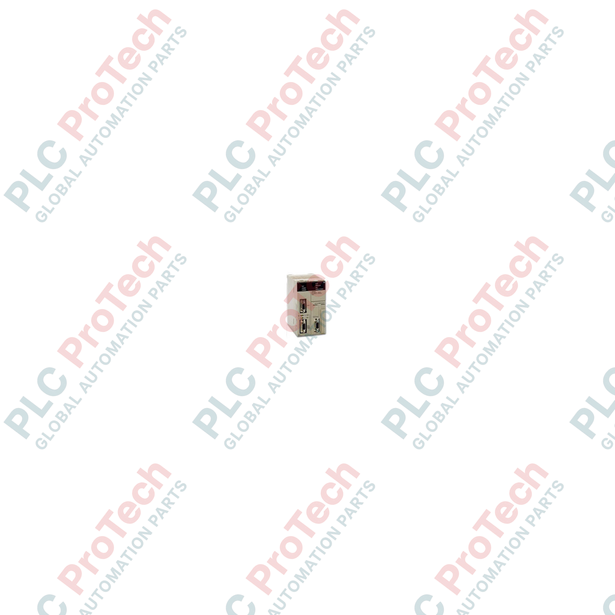
Executing complex industrial automation sequences, the Omron CS1H-CPU63H serves as a high-performance central processing unit within the modular CS1 series programmable logic controller architecture. This unit manages high-speed processing, large-scale data registration, and extensive I/O distribution across multiple expansion racks. Built to interface seamlessly with advanced motion control, serial communications, and network modules, the processor features dedicated peripheral and RS-232C interfaces for local maintenance, programming, and host link communications.
Features
- High-speed basic instruction execution down to 0.02 microseconds.
- Generous dual-port design featuring a standard RS-232C port and a dedicated peripheral port.
- Large memory allocation supporting structured text and ladder diagram configurations.
- Expandable physical architecture capable of addressing up to 7 expansion racks.
- Comprehensive diagnostic monitoring via integrated LED status indicators.
Applications
- High-speed packaging and assembly lines requiring fast PLC scan times.
- Water and wastewater treatment plants with distributed I/O systems.
- Automotive welding and conveyance cell control systems.
- Material handling and automated warehouse sorting systems.
Technical Specifications
| Specification Parameter |
Value / Details |
| Manufacturer |
Omron |
| Model Series |
CS1 Series (CS1H) |
| Program Capacity |
20 Ksteps |
| Data Memory Capacity |
64 Kwords (DM: 32 Kwords, EM: 32 Kwords x 1 bank) |
| I/O Points / Bits |
5,120 bits (Up to 7 Expansion Racks) |
| LD Instruction Processing Speed |
0.02 microseconds |
| Built-in Communication Interfaces |
Peripheral Port, RS-232C Port (D-sub 9-pin female) |
| Current Consumption |
1.10 A at 5 VDC |
| Operating Temperature Range |
0 to 55 degC |
| Country of Origin |
Japan |
| Shipping Weight (Calculated) |
0.55 kg (excluding packaging) / 2.50 kg (gross shipping weight) |
| Package Dimensions (Calculated) |
160 mm x 140 mm x 80 mm |
Connections and Interfaces
The integrated RS-232C interface utilizes a standard D-sub 9-pin female connector configured for serial communication, Modbus RTU, or host link connectivity. Pin assignments are structured as follows:
| Connector Pin / Terminal |
Signal Abbreviation |
Function / Circuit Assignment |
| Pin 1 |
FG |
Frame Ground (Shield Connection) |
| Pin 2 |
SD (TXD) |
Send Data / Transmit |
| Pin 3 |
RD (RXD) |
Receive Data |
| Pin 4 |
RS (RTS) |
Request to Send |
| Pin 5 |
CS (CTS) |
Clear to Send |
| Pin 9 |
SG (GND) |
Signal Ground |
Empirical Engineering Insights
Alternative Models & Compatibility
The CS1H-CPU63H is a direct successor to legacy CS1H-CPU63 modules. While backplane footprints remain identical, program migration to the 'H' suffix CPU requires CX-Programmer version 3.0 or higher to correctly access enhanced instruction sets and utilize the faster CPU bus speed characteristics.
Application Pitfalls & Engineering Notes
With an internal current draw of 1.10 A on the 5 VDC rail, system engineers must run a strict power-balance budget for the chosen backplane. Combining high-density input modules, analog units, and communication modules on the same chassis may cause voltage drops if using standard power supply units like the PA204. Upgrade to a PA207R power supply if the total internal 5 VDC demand exceeds 80% of the power supply's output rating.
Commissioning & Wiring Tips
The front dip switch cover conceals configuration switches. Set Dip Switch 4 to the 'OFF' position to use custom communication parameters for the RS-232C port. Leaving Switch 4 'ON' forces the port to default to standard host link auto-detect configuration, which can overwrite custom serial protocol parameters defined in the PLC setup parameters.
Installation Guidelines
CRITICAL WARNING
Do not insert or remove this central processing unit while the backplane power supply is turned on. Live-plugging will result in permanent damage to the CPU bus interface, internal flash memory corruption, or complete control system failure.
1
Isolate the primary incoming power source feeding the CS1 system power supply module and verify zero-voltage status.
2
Align the top and bottom guides of the CS1H-CPU63H module into the dedicated CPU slot (usually the leftmost slot next to the power supply unit).
3
Carefully push the unit straight into the backplane connector until the locking mechanisms click and lock securely into position.
4
Attach the standard ground wire to the backplane's grounding terminal and tighten the terminal to 1.2 N-m torque to prevent industrial EMI noise issues.