Description
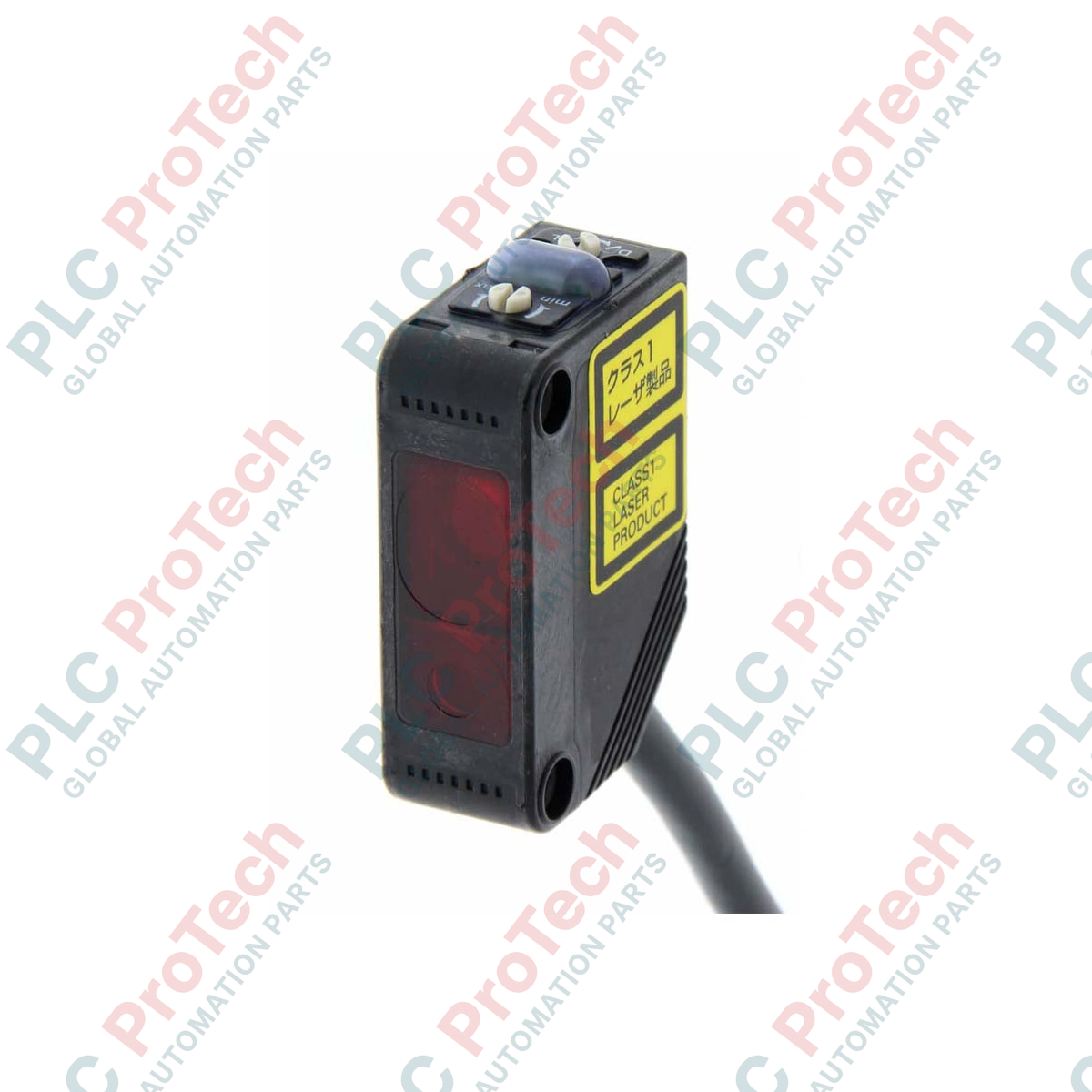
Providing precise distance-settable background suppression (BGS) in complex positioning setups, the Omron E3Z-LL81 photoelectric sensor uses a high-precision Class 1 red laser diode to achieve millimeter-level target detection. This sensor is engineered to ignore background objects beyond the set cutoff limit, delivering highly reliable object detection regardless of target color, gloss, or angle. With its ultra-concentrated 0.5-mm spot diameter at 300 mm, the device is ideal for electronic component verification, small parts detection, and high-speed automated packaging machinery.
Key Features
-
Class 1 Laser Diode: Safe 655 nm red laser light source requires no specialized eye shielding under standard operating conditions.
-
Advanced Background Suppression (BGS): Eliminates false triggers caused by highly reflective background surfaces or changing target colors.
-
Fine-Line Spot Accuracy: Tiny 0.5-mm diameter light spot permits detection of miniature objects and precise edge positioning.
-
Robust PNP Output: Open collector control output handles loads up to 100 mA at 26.4 VDC.
-
Industrial-Grade Housing: Compact design with IP67 sealing for reliable operation in wet or dusty processing environments.
Applications
- High-speed semiconductor and electronic component sorting.
- Product detection and positioning on automated packaging conveyors.
- Precise edge-guiding and register mark alignment in printing machinery.
- Small parts presence inspection in robotic assembly work cells.
Technical Specifications
| Parameter |
Specification |
| Manufacturer |
Omron |
| Model Number |
E3Z-LL81 |
| Sensing Method |
Distance-settable (BGS Models) |
| Sensing Distance (White Paper) |
20 to 300 mm (100 x 100 mm target) |
| Sensing Distance (Black Paper) |
20 to 160 mm (100 x 100 mm target) |
| Set Distance Range (White Paper) |
40 to 300 mm |
| Set Distance Range (Black Paper) |
40 to 160 mm |
| Light Source (Wavelength) |
Red LD (655 nm), JIS Class 1, IEC Class 1, FDA Class 2 |
| Spot Diameter (Reference Value) |
0.5 mm dia. at 300 mm |
| Power Supply Voltage |
12 to 24 VDC +/-10%, ripple (p-p): 10% max. |
| Current Consumption |
30 mA max. |
| Control Output |
PNP open collector, 26.4 VDC max., 100 mA max. load current |
| Shipping Weight (Calculated) |
1.00 kg (Includes protective factory packaging) |
| Package Dimensions (Calculated) |
150 x 100 x 50 mm |
Connections and Interfaces
| Wire Color |
Function / Assignment |
| Brown |
Power Supply (+V, 12 to 24 VDC) |
| Blue |
Power Supply (0V / GND) |
| Black |
Control Output (PNP Open Collector) |
| Pink |
Control Input (Light-ON / Dark-ON Selection) |
Alternative Models & Compatibility
The E3Z-LL81 features a PNP open collector output. If your control system requires an NPN configuration, use the E3Z-LL61 alternative model. Mounting dimensions and sensing ranges are identical across both models, allowing direct physical drop-in replacements during system integration or logic retrofits.
Application Pitfalls & Engineering Notes
When deploying the sensor in environments with highly reflective metal or mirrored backgrounds situated near the sensing field, reflection off the background may bypass the BGS cutoff. To counteract this optical feedback, mount the sensor at an angle of 5 to 10 degrees relative to the target surface. Avoid placing the sensor in direct sunlight or facing heavy high-frequency discharge light sources, which can disrupt the receiver circuit.
Commissioning & Wiring Tips
To configure the output mode of the sensor, use the integrated Pink control wire. Connecting the Pink wire to the Brown wire (+V) configures the sensor for Dark-ON operation, whereas connecting it to the Blue wire (0V) or leaving it open configures it for Light-ON operation. Verify current limits prior to termination to prevent over-current damage to the internal PNP transistor.
Installation Guidelines
CRITICAL WARNING
Disconnect all power distribution sources prior to making electrical connections or mechanical adjustments. Do not look directly into the laser transmitter lens while the sensor is powered, as direct laser exposure can cause eye irritation or optical damage.
1
Securely mount the sensor using a compatible Omron L-bracket or direct machine frame mount, ensuring that the optical path to the target is clear of physical obstructions.
2
Wire the sensor according to the electrical schematic. Ensure the Pink wire is tied to the appropriate potential (+V or 0V) to define your required operation mode (Light-ON or Dark-ON).
3
Apply 12 to 24 VDC power and verify that the green stability indicator remains lit under non-sensing conditions, signifying healthy signal headroom.
4
Place the target object at the maximum desired detection distance and adjust the integrated multi-turn distance adjuster screw until the orange operation indicator illuminates.