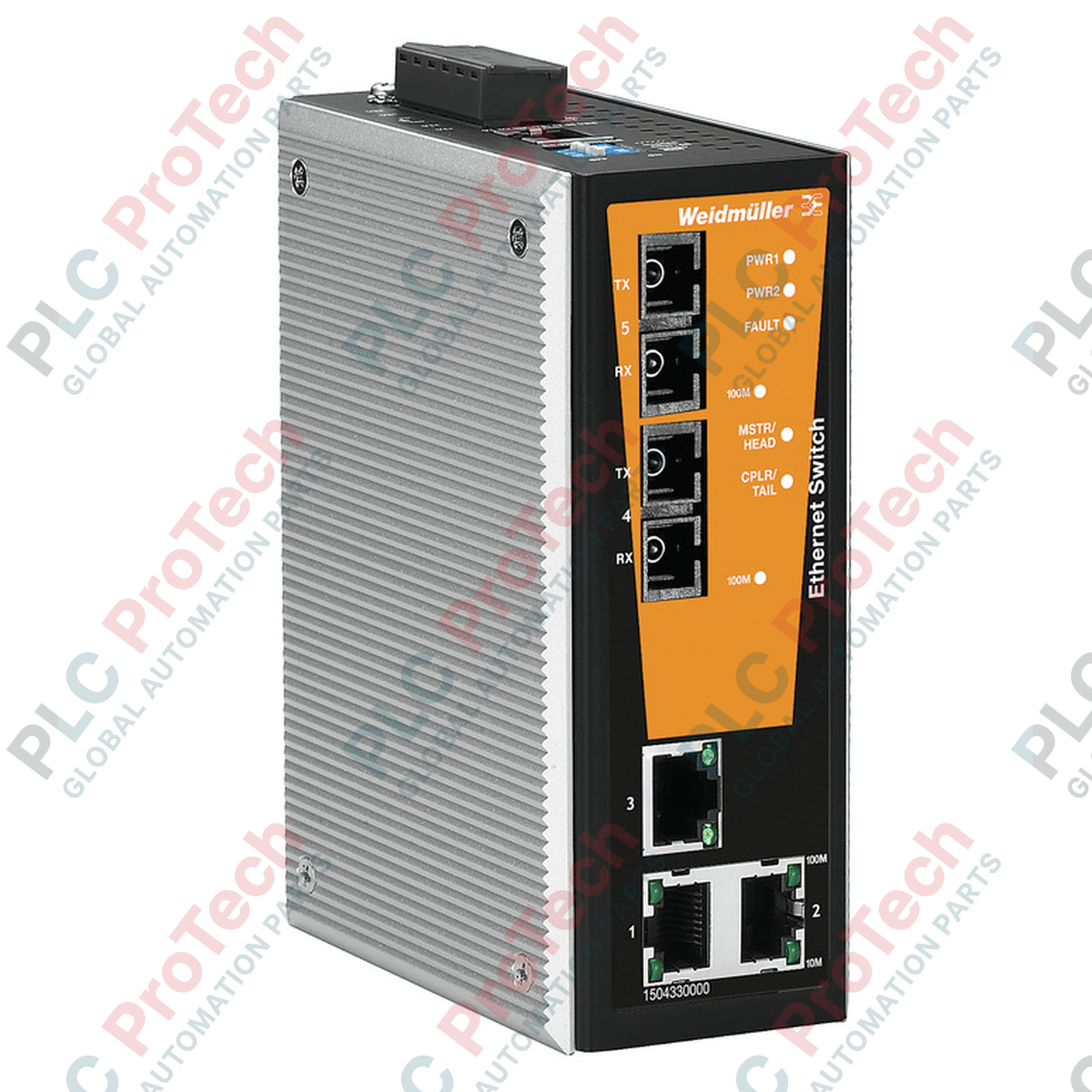
Entwickelt, um zuverlässige Kommunikationsverbindungen in störungsintensiven Umgebungen aufrechtzuerhalten, ist der Weidmuller 1504350000 IE-SW-VL05MT-3TX-2SC ein verwalteter ValueLine Industrial Ethernet Switch mit drei RJ45-Ports und zwei Multimode SC-Duplex-Glasfaseranschlüssen. Dieses Gerät bietet robustes Netzwerkmanagement, Ringredundanz und Verkehrspriorisierung direkt auf Feldebene, was es ideal für kritische Infrastrukturen und anspruchsvolle Automatisierungsnetzwerke macht.
Hauptmerkmale
-
Managed Netzwerksteuerung: Unterstützt wesentliche Managementfunktionen wie VLAN, QoS, IGMP Snooping und Port-Mirroring für optimierte Bandbreitenkontrolle.
-
Glasfaseranschluss: Ausgestattet mit zwei 100BaseFX Multimode-Glasfaseranschlüssen mit SC-Duplex-Steckern für störungsfreie Datenübertragung bis zu 5 km.
-
Großer Temperaturbereich: Zertifiziert für den Betrieb in extremen Umgebungen von -40 °C bis 75 °C ohne aktive Kühlung.
-
Redundante Stromeingänge: Doppelte 12/24/48 V DC Stromeingänge gewährleisten den kontinuierlichen Betrieb bei Ausfall der Hauptstromversorgung.
-
Industriegehäuse: Untergebracht in einem robusten Metallgehäuse mit IP30-Schutz, das hohen mechanischen Stößen und Vibrationen standhält.
Anwendungen
- Netzwerke zur Überwachung von Windkraftanlagen und Solarfarmen.
- Steuerungssysteme für Wasser- und Abwasseranlagen.
- Fabrikautomation und Maschine-zu-Maschine (M2M) Kommunikation.
- Überwachung von Öl- und Gaspipelines sowie verteilte RTU-Netzwerke.
Technische Spezifikationen
| Parameter |
Wert |
| Hersteller |
Weidmuller |
| Artikelnummer / SKU |
1504350000 |
| Modelltyp |
IE-SW-VL05MT-3TX-2SC |
| Switch-Typ |
Managed (ValueLine) |
| RJ45-Anschlüsse |
3x 10/100BaseT(X), automatische Aushandlung, Vollduplex/Halbdüplex, Auto MDI/MDI-X |
| Glasfaseranschlüsse |
2x 100BaseFX, Multimode, SC-Duplex-Stecker |
| Übertragungsdistanz |
5 km (typisch über 50/125 oder 62,5/125 µm Multimode-Faser) |
| Wellenlänge |
1310 nm |
| Eingangsspannung |
12 / 24 / 48 V DC (redundante Eingänge) |
| Betriebstemperatur |
-40 °C bis 75 °C |
| Lagertemperatur |
-40 °C bis 85 °C |
| Umgebungsfeuchtigkeit |
5 % bis 95 % (nicht kondensierend) |
| MAC-Tabellengröße |
2 K |
| Puffergröße für Pakete |
1 Mbit |
| Gehäusematerial |
Metall (Schutzart IP30) |
| Montageart |
Hutschiene (TS 35), Schalttafelmontage (mit optionalem Kit) |
| Abmessungen (B x H x T) |
53,6 mm x 135 mm x 105 mm |
| Nettogewicht |
650 g |
| Versandgewicht (berechnet) |
1,5 kg |
Anschlüsse und Schnittstellen
| Anschluss-Pin |
Signalbelegung |
Beschreibung |
| Pin 1 |
V1+ |
DC-Stromeingang 1 (Positiv) |
| Pin 2 |
V1- |
DC-Stromeingang 1 (Negativ / Gemeinsamer Anschluss) |
| Pin 3 |
STATE (NC) |
Fehler-Relaisausgang (Normalerweise geschlossen) |
| Pin 4 |
STATE (COM) |
Fehler-Relaisausgang (Gemeinsamer Anschluss) |
| Pin 5 |
V2+ |
DC-Stromeingang 2 (Positiv) |
| Pin 6 |
V2- |
DC-Stromeingang 2 (Negativ / Gemeinsamer Anschluss) |
Alternative Modelle & Kompatibilität
Dieser verwaltete Switch dient als direkte Aufrüstung der unmanaged IE-SW-VL05-3TX-2SC-Serie und bietet erweiterte Diagnosen sowie Ringredundanzprotokolle (wie Turbo Ring oder RSTP) zur Vermeidung von Netzwerkschleifen. Beim Austausch älterer Revisionen prüfen Sie, ob die vorhandene Netzwerkmanagement-Software oder PLC-Konfiguration standardmäßiges SNMP oder die spezifischen Weidmuller-Ringtopologieparameter unterstützt.
Anwendungsfallen & technische Hinweise
Beim Einsatz der Multimode-SC-Duplex-Anschlüsse über lange Distanzen darf das gesamte optische Leistungsbudget die Sättigungsgrenzen des Empfängers nicht überschreiten. Für kurze Glasfaserverbindungen (unter 100 Metern) sind optische Dämpfungsglieder in der Regel nicht erforderlich, jedoch sind saubere Glasfaserendflächen entscheidend, um Paketverluste zu vermeiden. Stellen Sie sicher, dass der Switch vertikal auf der DIN-Schiene montiert ist, um eine natürliche Konvektionskühlung zu ermöglichen, insbesondere bei Betrieb nahe der oberen thermischen Grenze von 75 °C.
Inbetriebnahme- & Verdrahtungstipps
Um elektromagnetische Verträglichkeit (EMV) sicherzustellen, verbinden Sie den Funktionserdeanschluss (FE) am DIN-Schienen-Erdeblock direkt mit einer niederohmigen Erdung. Verwenden Sie beim Verdrahten der redundanten Stromzuführungen einen Drahtquerschnitt zwischen 12 und 24 AWG. Ziehen Sie die Schrauben des Klemmenblocks mit einem Drehmoment von 0,5 Nm an, um lockere Verbindungen bei starken Vibrationen zu vermeiden.
Installationsrichtlinien
KRITISCHE WARNUNG
Schalten Sie alle Stromquellen aus, bevor Sie den 6-poligen Klemmenblock anschließen oder trennen. Führen Sie keine Glasfaserkabel ein oder ziehen Sie sie heraus, während der Transceiver aktiv ist, um mögliche Augenverletzungen durch unsichtbare Laserstrahlung zu vermeiden.
1
Klicken Sie den Switch auf die TS 35 DIN-Schiene, wobei der obere Haken zuerst einrastet, und drücken Sie dann den unteren Teil des Geräts, bis die Metallverriegelung sicher einrastet.
2
Verbinden Sie den Funktionserdeanschluss mit dem lokalen Schutzerdungssystem mittels eines kurzen, dickeren Drahtes.
3
Stecken Sie die RJ45-Kupfernetzwerkkabel und die SC-Duplex-Multimode-Glasfaserkabel in die dafür vorgesehenen Anschlüsse, bis sie einrasten.
4
Schließen Sie die redundanten Netzteile an den 6-poligen Klemmenblock an, stecken Sie den Block in den Switch und schalten Sie die Stromversorgung ein, um den Status über die LED-Anzeigen an der Frontplatte zu überprüfen.