Description
Designed for continuous machinery vibration monitoring in demanding industrial thermal conditions, the Bently Nevada 74712-06-05-02-00 provides precise case velocity measurements on critical rotating machinery. This high-temperature, two-wire transducer operates on moving-coil design principles, generating a voltage proportional to the vibration velocity without requiring external power. The specific configuration of this 74712 Seismoprobe model makes it highly suitable for structural vibration analysis on gas turbines, steam turbines, pumps, and fans where operating temperatures exceed standard sensor limits.
Features
-
Two-Wire Construction: Simplifies wiring infrastructure and integrates directly with traditional machinery protection systems.
-
Horizontal Optimization: Calibrated for a horizontal mounting orientation (0 deg plus/minus 100 deg) with a 10 Hz minimum operating frequency.
-
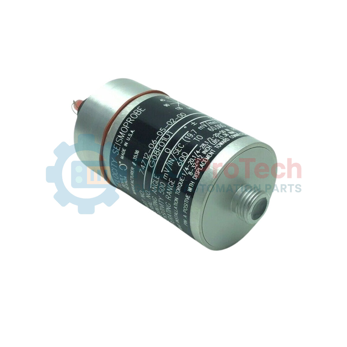
Integrated Stud Mount: Direct attachment via a 1/2-20 UNF-3A stud, maximizing mechanical high-frequency transmission.
-
Top-Mount Connector: Minimizes overall physical clearance requirements in tight machine enclosures.
Applications
- High-temperature exhaust fans and industrial blowers
- Heavy-duty steam and gas turbine bearing housing monitoring
- Main boiler feed pumps and safety-critical pumping systems
- Rotary compressors and high-speed gearboxes
Ordering Information
| Option Code |
Option Type |
Selected Configuration Description |
| 06 |
Mounting Angle / Operating Frequency |
0 deg +/- 100 deg, 10 Hz (600 cpm) minimum operating frequency |
| 05 |
Mounting Base |
No base; 1/2-20 UNF-3A stud connection |
| 02 |
Connector Option |
Top Mount |
| 00 |
Agency Approval |
No Approvals |
Technical Specifications
| Manufacturer |
Bently Nevada (Baker Hughes) |
| Model Series |
74712 High-Temperature Seismoprobe |
| Full Part Number |
74712-06-05-02-00 |
| Transducer Type |
Self-generating, moving-coil velocity sensor |
| Mounting Angle |
0 deg +/- 100 deg (Horizontal mounting target) |
| Minimum Frequency |
10 Hz (600 cpm) |
| Mechanical Connection |
1/2-20 UNF-3A integral stud mount |
| Electrical Connection |
Top-mounted multi-pin connector |
| Hazardous Area Certifications |
None (Option 00) |
| Transducer Weight |
480 grams (17 ounces) typical |
| Shipping Weight (Calculated) |
1.5 kg (3.3 lbs) |
Empirical Engineering Insights
Alternative Models & Compatibility
The 74712 series serves as a specialized, high-temperature replacement for standard velocity sensors such as the Bently Nevada 9200. Ensure that the associated monitoring system configuration (e.g., Bently Nevada 3500/42M) matches the expected electrical characteristics and low-frequency cut-off values of the 74712 transducer.
Application Pitfalls & Engineering Notes
The "06" option dictates a horizontal mounting angle constraint. Attempting to install this unit vertically (90 degrees relative to horizontal) will cause the internal moving coil to rest off-center, leading to signal clipping, measurement errors, and premature internal mechanical wear. Operating temperature ranges must be kept within the physical limits of the transducer's internal assemblies to prevent coil insulation degradation.
Commissioning & Wiring Tips
When routing cables from the top-mount connector, provide an adequate drip loop and strain relief. High-temperature environments generate mechanical stress, so armored, shielded cables should be securely tied down to structural points nearby rather than being allowed to hang from the connector head.
Installation Guidelines
CRITICAL WARNING
Isolate the machine and ensure it is in a zero-energy state before drilling, tapping, or mounting the sensor. Physical impact or excessive torque applied directly to the transducer body during installation can permanently damage the internal moving-coil alignment.
1
Prepare a clean, flat surface on the bearing housing perpendicular to the desired measurement axis.
2
Verify that the mounting thread matches the 1/2-20 UNF-3A stud specification precisely.
3
Apply thread-locking compound if required by plant specifications, and torque the transducer base using the flat wrench surfaces only. Do not torque by gripping the sensor body.
4
Attach the top-mount connector and secure the cable shield to the designated monitoring rack ground to prevent electro-magnetic interference.