Description
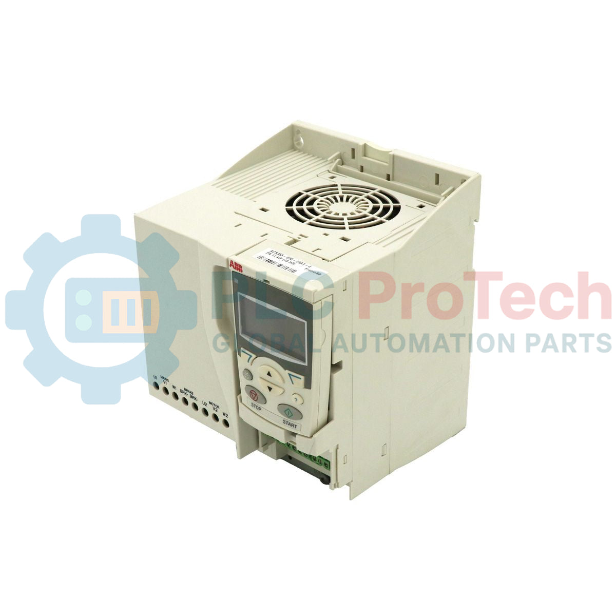
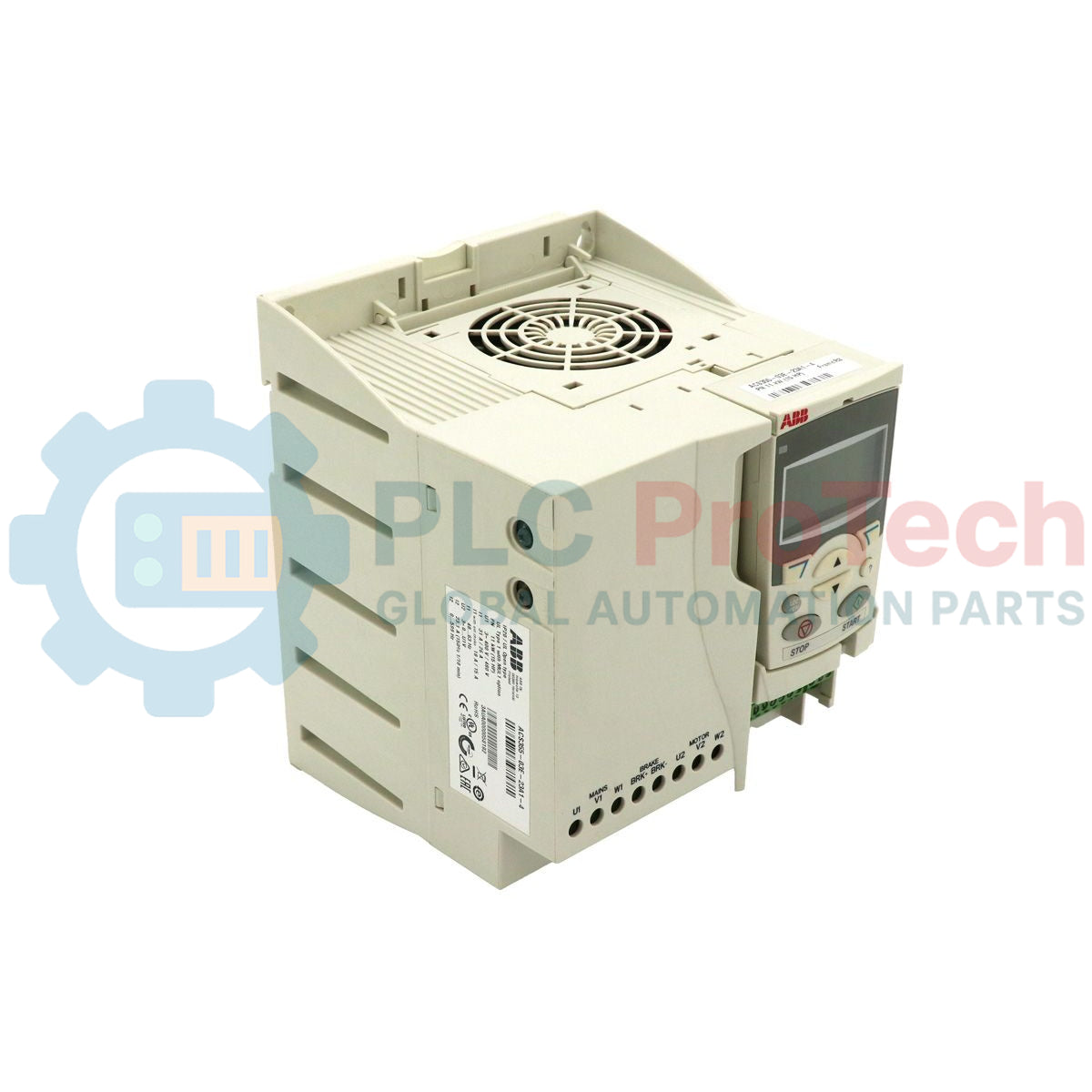
Designed to deliver precise speed and torque control for low-voltage AC motor applications, the ABB ACS355-03E-23A1-4 variable frequency drive serves as a high-performance system component within the ACS355 series. This three-phase machinery drive handles demanding production environments with integrated Safe Torque Off (STO) capabilities, dynamic braking options, and optimized IP20 cabinet compatibility. Engineered for seamless integration into industrial panels, this drive ensures reliable operation under varying mechanical loads and maintains exceptional efficiency throughout its operational life cycle.
Features
-
Safe Torque Off (STO): Built-in dual-channel safety system certified up to SIL3 / PL e, eliminating the need for external redundant contactors.
-
Flexible Motor Control: Supports both scalar (V/Hz) and vector (sensorless) control algorithms to optimize torque performance at low speeds.
-
Integrated Brake Chopper: Standard built-in dynamic braking transistor allows direct connection of external braking resistors for decel control.
-
Cabinet Optimization: Symmetrical IP20 enclosure design allows direct side-by-side DIN-rail or screw mounting without lateral clearance requirements.
-
Sequence Programming: Built-in independent logic sequence programming enables the drive to perform basic automation tasks without a separate micro-PLC.
Applications
-
Conveyor Systems: Precise speed control and high starting torque handling under heavy physical loading.
-
Mixers and Agitators: Vector control mode dynamically compensates for viscosity changes in process mixtures.
-
Pumping and Ventilation: Quadratic load curves optimize energy savings in commercial air handling and fluid transport.
-
Packaging Equipment: High-speed digital inputs and dynamic braking enable quick cycle response times.
Technical Specifications
| Manufacturer |
ABB |
| Model Number |
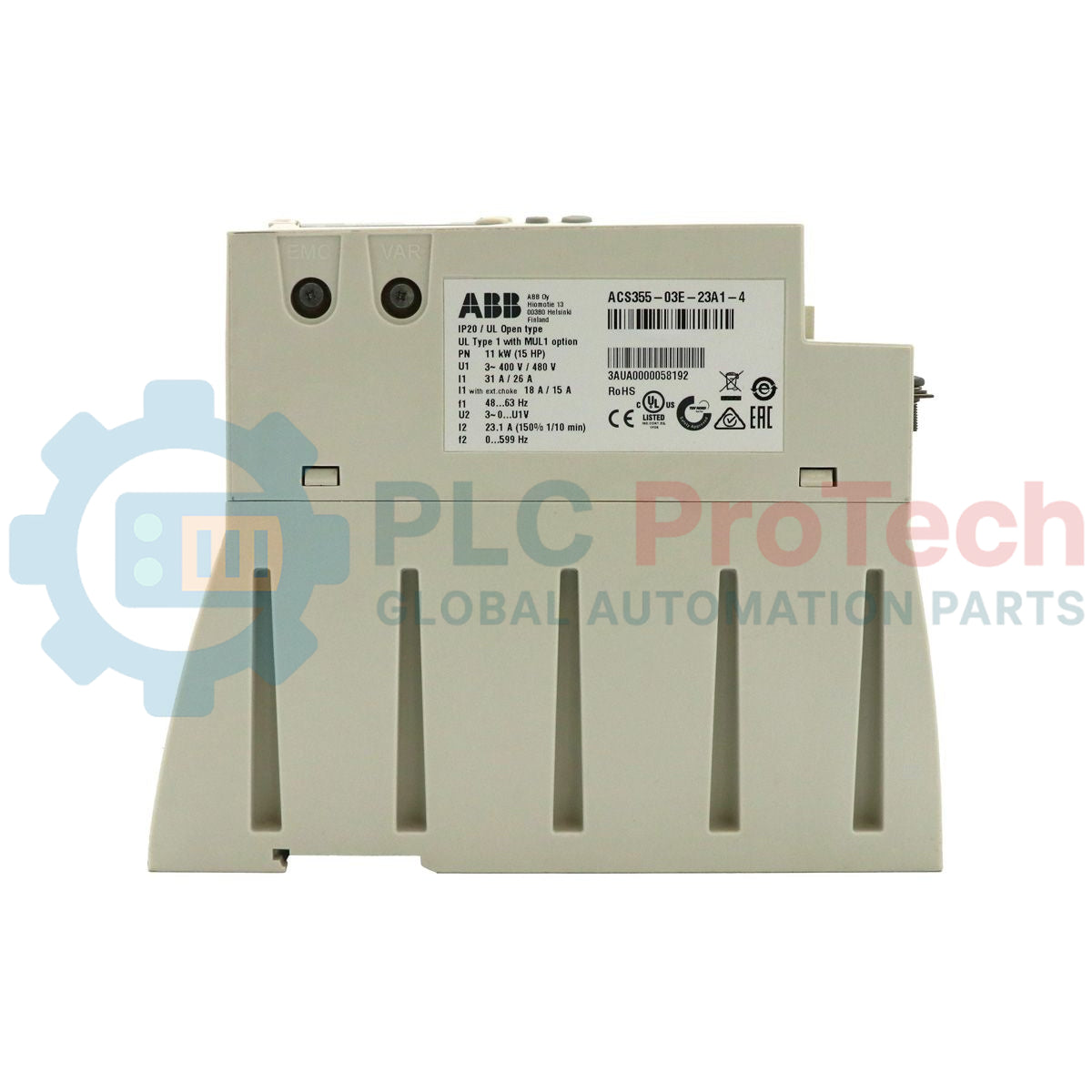
ACS355-03E-23A1-4 |
| Product Series |
ACS355 |
| Input Voltage |
380 to 480 VAC (3-Phase, +/-10%) |
| Output Current (Normal Use) |
23.1 A |
| Output Power (Normal Use) |
11 kW (15 HP) |
| Output Frequency Range |
0 to 600 Hz |
| Enclosure Rating |
IP20 (Open Type) |
| Frame Size |
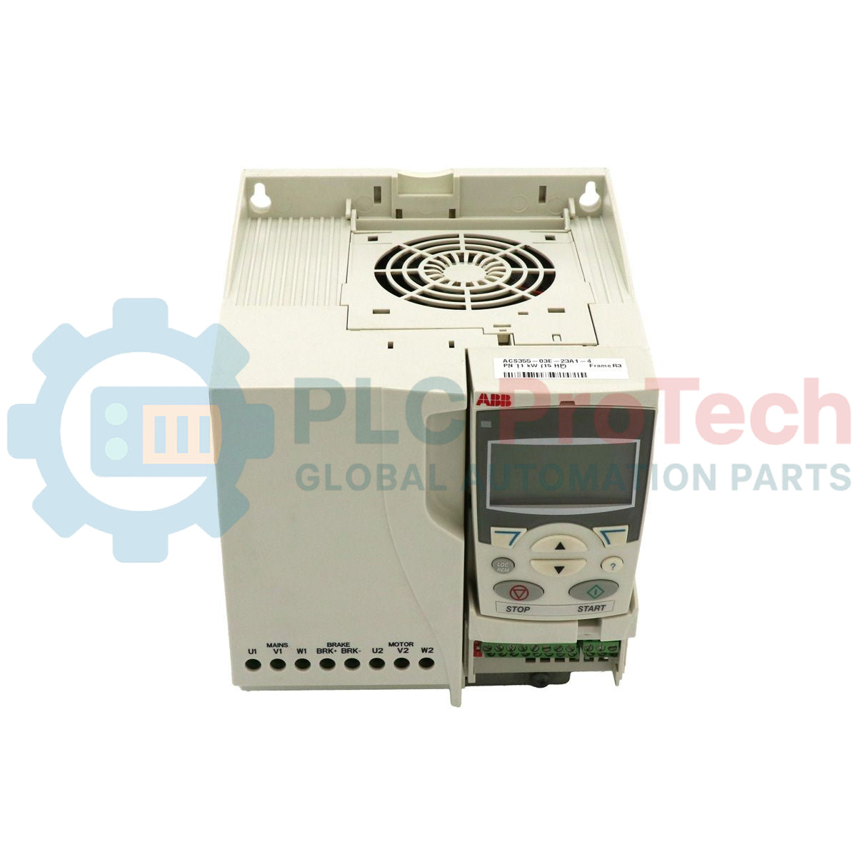
R3 |
| Physical Dimensions |
169 x 169 x 169 mm |
| Shipping Weight |
2.50 kg (5.51 lbs) |
| Commodity Code |
85044095 |
Connections and Interfaces
| Terminal Block |
Terminal Name |
Default Function Assignment |
| Analog I/O |
AI1 / AI2 / AO |
Speed Reference Input / Auxiliary Reference Input / Motor Speed Output |
| Digital Inputs |
DI1 to DI5 |
Start/Stop, Reverse, Constant Speed Select, Acceleration/Deceleration Ramps |
| Auxiliary Voltage |
+24V / DCOM |
Auxiliary voltage output and Digital ground reference |
| Relay Outputs |
RO1 (C/O) |
Fault / Ready signalization (Form C relay output) |
| Safety Terminal |
OUT1 / OUT2 / IN1 / IN2 |
Dual-channel Safe Torque Off (STO) circuit loop |
Empirical Engineering Insights
Alternative Models & Compatibility: The ACS355 series represents an evolutionary upgrade over legacy ACS350 drives. Standard parameter configurations can be transferred directly between equivalent frame sizes via the handheld ABB FlashDrop tool. If replacing a standard ACS350, verify PLC fieldbus mapping configurations, as the ACS355 offers expanded fieldbus adapter compatibility profiles.
Application Pitfalls & Engineering Notes: When mounting IP20 drives inside high-density enclosures, thermal management is key. Even though the ACS355 supports side-by-side mounting, a minimum of 75 mm of vertical clearance is required above and below the cooling fan assembly to prevent internal thermal hotspots and premature fault codes like F0009 (Overtermperature).
Commissioning & Wiring Tips: To utilize the built-in STO safety feature, both physical STO input channels (IN1 and IN2) must switch state simultaneously within a 250 ms time frame. An asymmetric trigger caused by poor auxiliary contact timing on physical safety relays will trigger fault code F0021 (STO validation fault) on the keypad screen.
Installation Guidelines
CRITICAL WARNING
Risk of electric shock. Ensure all AC main power feeds are physically disconnected and locked out. Allow a minimum of 5 minutes for the internal DC bus capacitors to discharge to safe levels before removing the cover or starting wiring procedures. Always verify zero voltage status with a certified multimeter.
1
Mount the drive vertically on a flat, non-flammable surface using the correct frame-size mounting brackets.
2
Verify the power line input parameters match the specifications label (3-phase 380 to 480 VAC).
3
Connect the incoming power supply wires to terminals U1, V1, and W1. Connect the motor supply cable to terminals U2, V2, and W2 utilizing high-integrity shielded cabling.
4
Terminate control and STO safety loops using recommended shielded multi-conductor cables to maintain electromagnetic compatibility (EMC).
5
Securely ground the drive frame directly to the main cabinet ground bus using an appropriate low-impedance ground strap.