Description
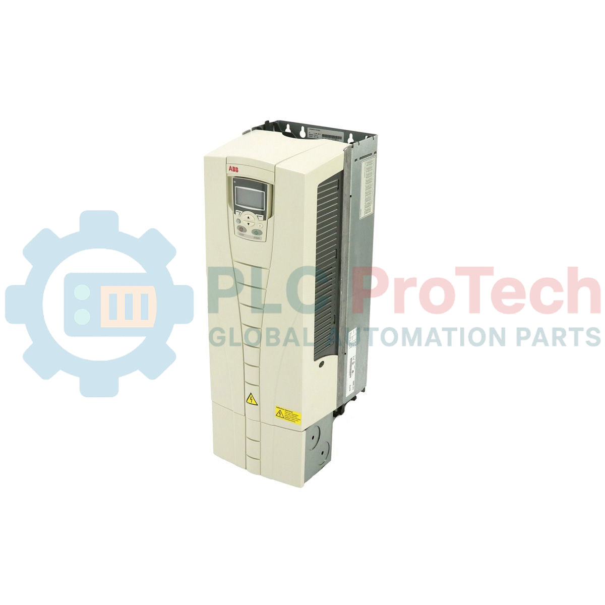
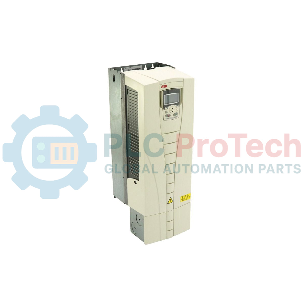
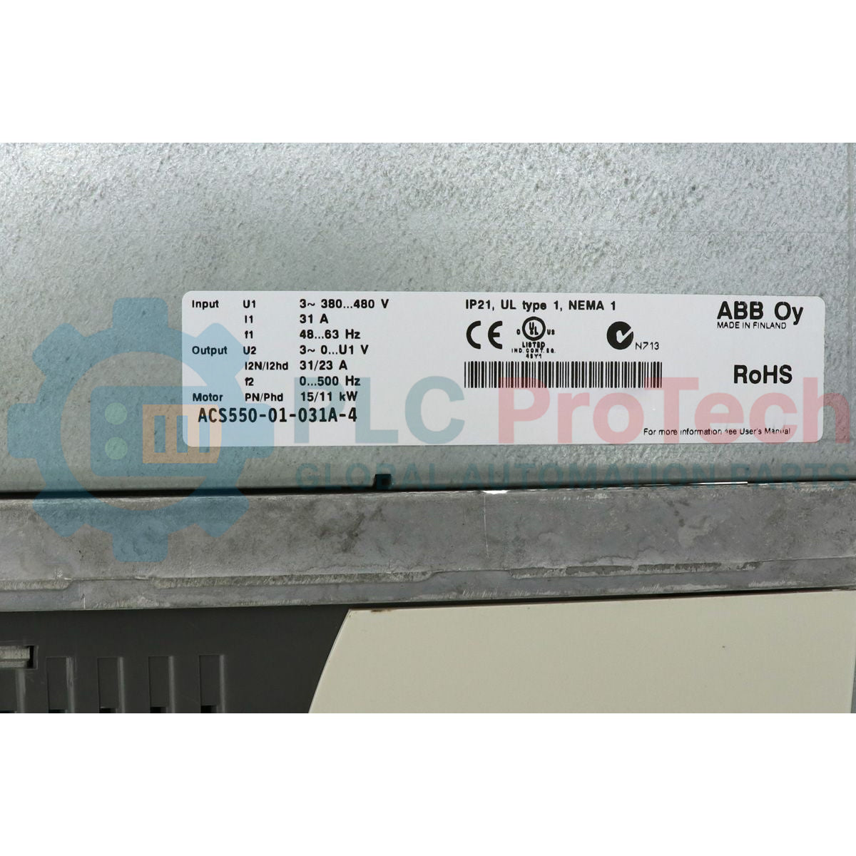
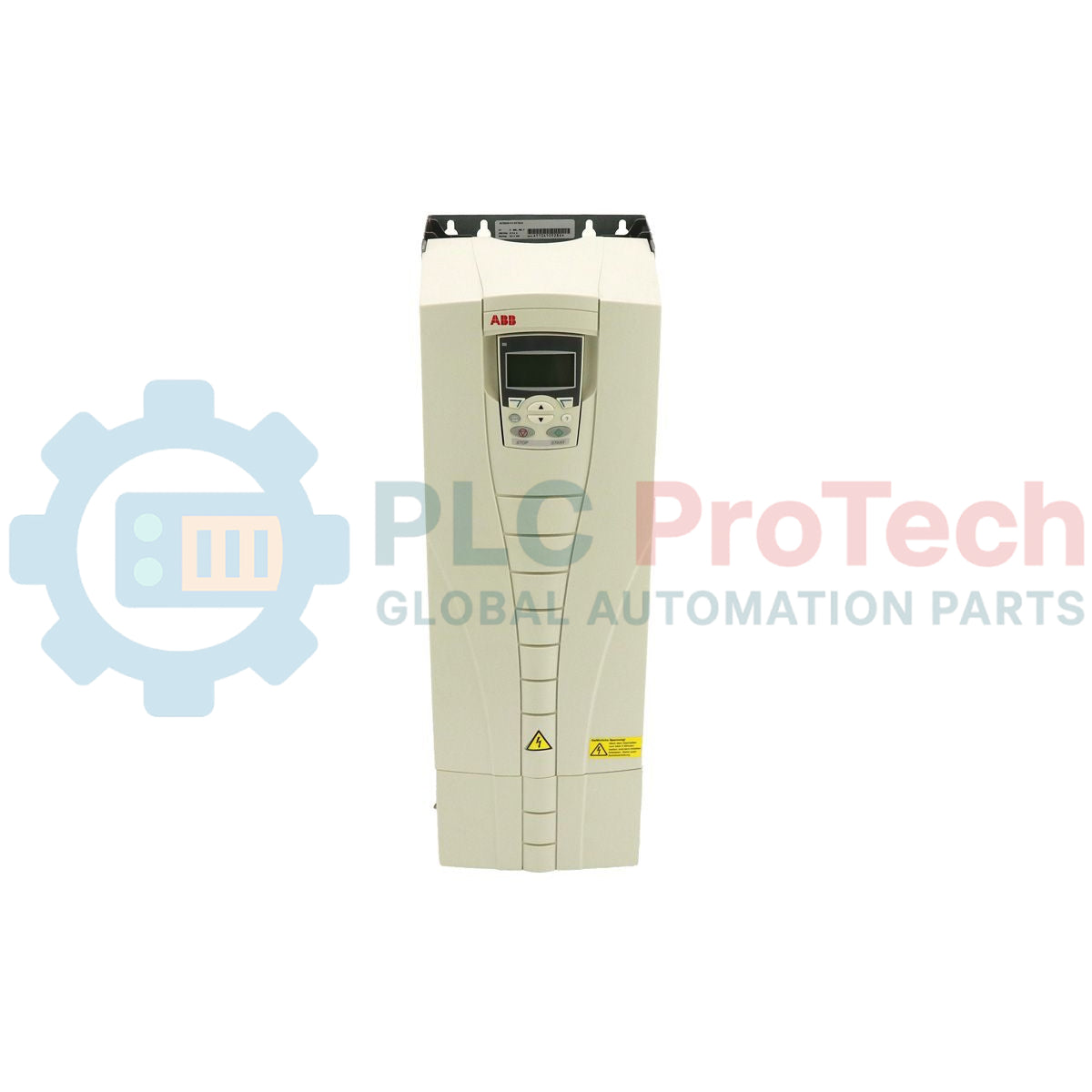
Managing three-phase motor performance in demanding automation systems is optimized using the ABB ACS550-01-031A-4 variable frequency drive, which supplies a nominal output current of 31 Amps and 15 kW (20 HP) of normal-duty shaft power. Engineered as an industrial-grade AC drive, this model operates on an input voltage range of 380 to 480 V AC, ensuring steady performance under fluctuating line conditions. The physical frame incorporates an integrated patented swinging choke design that significantly reduces supply line harmonics under both partial and full load conditions. Encased in a protective IP21 enclosure class, it is optimized for clean, wall-mounted indoor vertical installations, enabling close-coupled motor speed and torque regulation across various mechanical processes.
Features
- Advanced scalar and vector motor control models to accommodate both constant and variable torque loads.
- Integrated swinging choke design providing up to 25% lower low-frequency harmonics compared to traditional reactors.
- Built-in standard Modbus RTU interface with expansion slots for optional fieldbus communication adapters.
- Internal EMC filter as a standard component to limit electromagnetic emission and radio frequency interference.
- Dedicated assistant control panel featuring multi-language support, real-time diagnostic helpers, and parameter backup capabilities.
- Coated electronic circuit boards for improved reliability and resistance to industrial dust and ambient humidity.
Applications
- Centrifugal pumps and high-volume water distribution booster systems.
- Industrial ventilation fans, exhaust systems, and variable air-volume (VAV) air-handling units.
- Bulk material handling conveyors and packaging line sorting belts.
- Rotary screw air compressors and positive displacement industrial pumps.
Technical Specifications
| Parameter |
Specification Value |
| Manufacturer |
ABB |
| Model Code |
ACS550-01-031A-4 |
| Product Series |
ACS550 Standard Drive |
| Input Voltage Range |
380 to 480 V AC (+10% / -15%) |
| Number of Phases |
3-Phase |
| Input Frequency |
48 to 63 Hz |
| Nominal Output Current (Normal Use) |
31.0 Amps |
| Nominal Output Current (Heavy Duty) |
24.6 Amps |
| Output Power (Normal Use) |
15 kW (20 HP) |
| Output Power (Heavy Duty) |
11 kW (15 HP) |
| Frame Size |
R3 |
| Enclosure Class |
IP21 (UL Type 1) |
| Ambient Operating Temperature |
-15 to +40 degC (No frost allowed; up to +50 degC with current derating) |
| Efficiency (at nominal power) |
97.5% |
| Dimensions (H x W x D) |
583 mm x 203 mm x 231 mm |
| Net Shipping Weight |
16.00 kg |
| Country of Origin |
Finland |
Connections and Interfaces
| Terminal Block Designation |
Functional Assignment / Wiring Parameter |
| U1, V1, W1 |
3-Phase AC mains input power connection terminals |
| U2, V2, W2 |
3-Phase AC variable frequency output to induction motor |
| UDC+, UDC- |
Internal DC intermediate bus connections (for dynamic brake chopper modules) |
| PE (Grounding Terminals) |
Protective Earth terminals for input feed and output motor cable shield |
| X1-1 to X1-6 (Analog I/O) |
AI1 (Speed Ref), AI2 (Process Ref), AO1 (Frequency), AO2 (Current), 10V Reference, AGND |
| X1-9 to X1-18 (Digital I/O) |
DI1 (Start/Stop), DI2 (Fwd/Rev), DI3 to DI6 (Preset Speeds / Ramp select), +24V Aux Output |
| X1-19 to X1-27 (Relay Outputs) |
Three programmable relay outputs (RO1: Ready, RO2: Running, RO3: Fault / Active Disturbance) |
Empirical Engineering Insights
Alternative Models & Compatibility
This R3-frame unit functions as a direct drop-in replacement for older ACS550-01-031A-4 drives. If migrating parameter configurations via the assistant control panel (ACS-CP-A) from older versions of the drive, ensure that the target drive firmware matches the source version to prevent "Incompatible Parameter" transfer faults.
Application Pitfalls & Engineering Notes
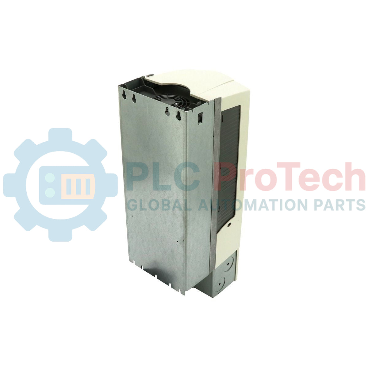
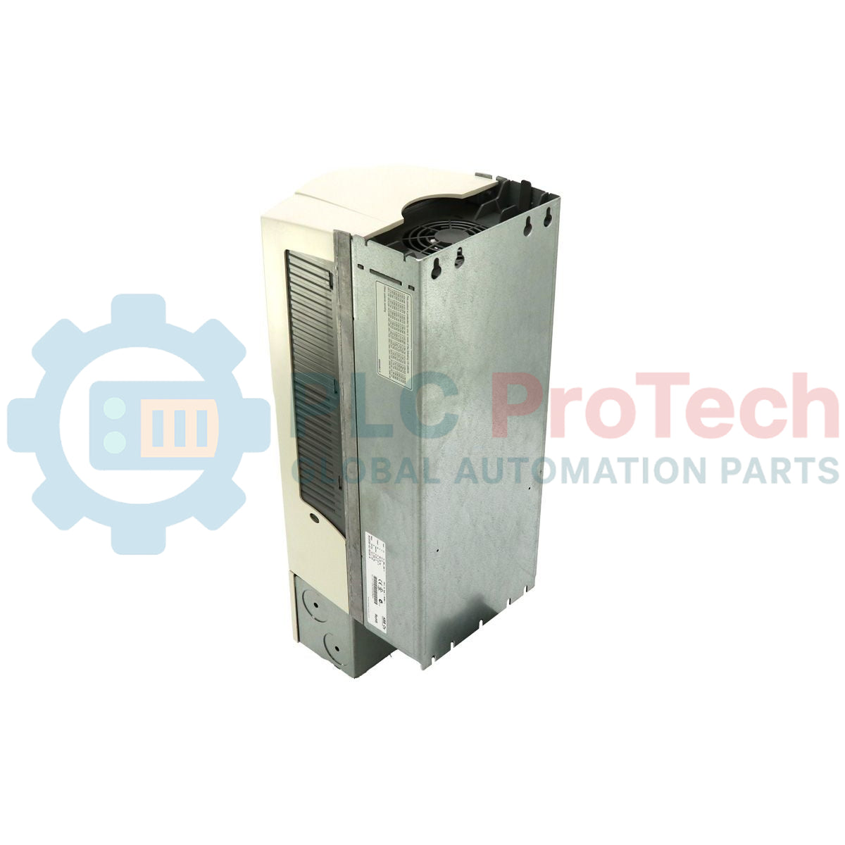
Frame R3 thermal design relies on efficient forced-air convection. The cooling fan draws air from the bottom; thus, maintaining a minimum clearance of 200 mm above and below the VFD chassis is mandatory. Running this model inside unventilated, high-heat panels without dynamic thermal calculation will cause overtemperature faults (Fault 9: MOTOR OVERTEMP or Fault 3: DEV OVERTEMP) due to heat accumulation on the internal heatsink.
Commissioning & Wiring Tips
When running on IT networks (ungrounded delta systems), the internal EMC filter must be disconnected by removing the internal EMC grounding screw. Failure to disconnect this filter on an ungrounded system will ground the drive's internal capacitors, causing fatal damage to the input varistors and input bridge rectifier.
Installation Guidelines
CRITICAL WARNING: HIGH VOLTAGE HAZARD
Isolate all electrical feeds prior to removing the front enclosure cover. After de-energizing, wait a minimum of 5 minutes for the internal DC intermediate bus capacitors to discharge. Measure voltage across terminals UDC+ and UDC- using a calibrated voltmeter to ensure potential is below 50 V DC before starting physical service or terminal block termination.
1
Mount the drive vertically to a flat, non-flammable backplate within an enclosure designed to meet the site ambient requirements.
2
Run input power cables and output motor cables in separate steel conduits to mitigate high-frequency cross-coupling and electrical noise injection.
3
Terminate 3-phase incoming power to U1, V1, W1 and dynamic brake/motor lines to U2, V2, W2. Torque terminals according to standard frame R3 specification requirements.
4
Ground the drive frame using the dedicated PE grounding terminal, and connect the low-voltage control analog/digital signaling using shielded twisted pair cables terminated to the control terminal block.