Description
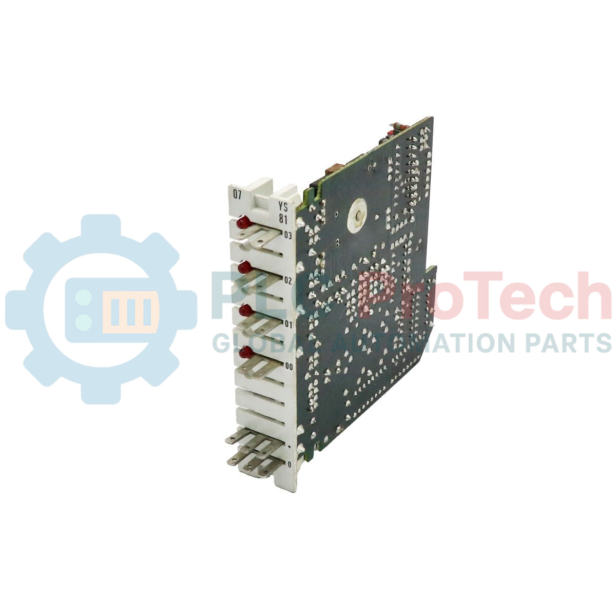
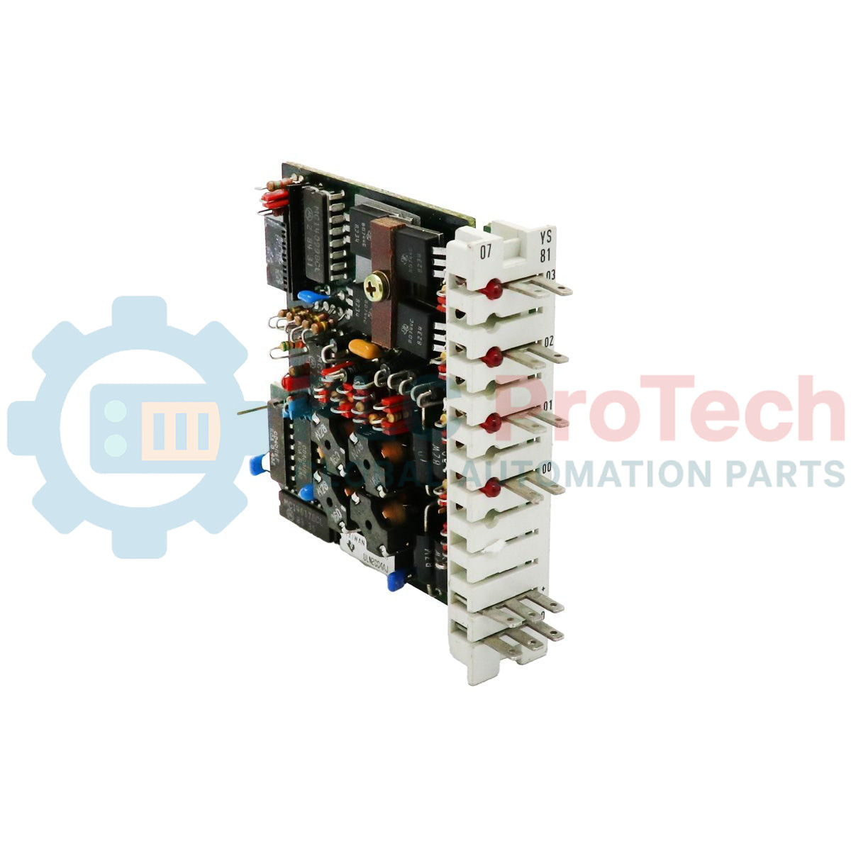
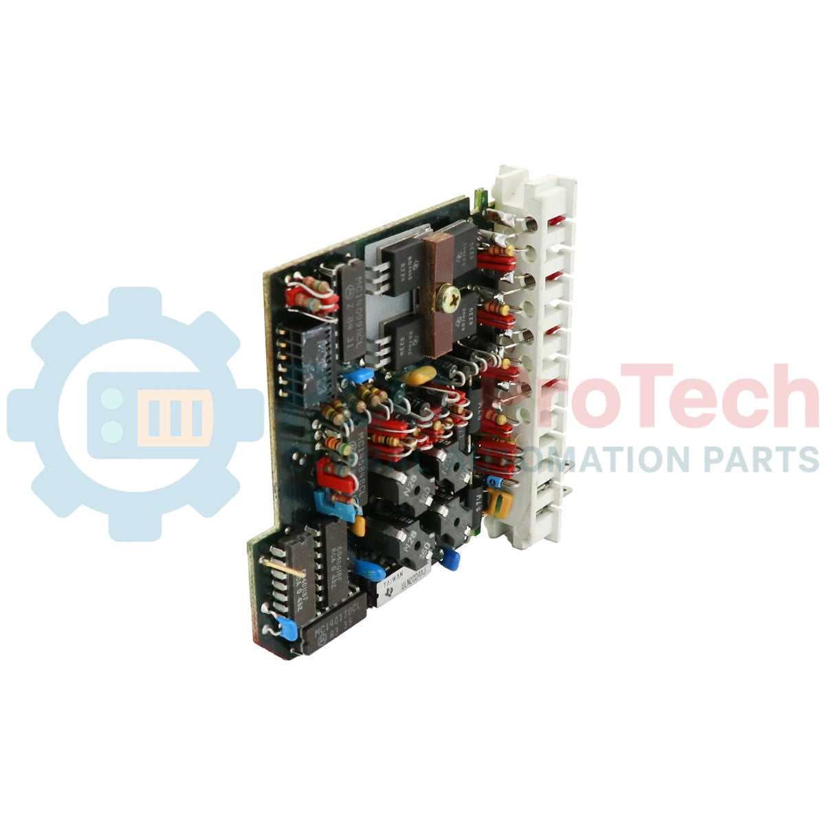
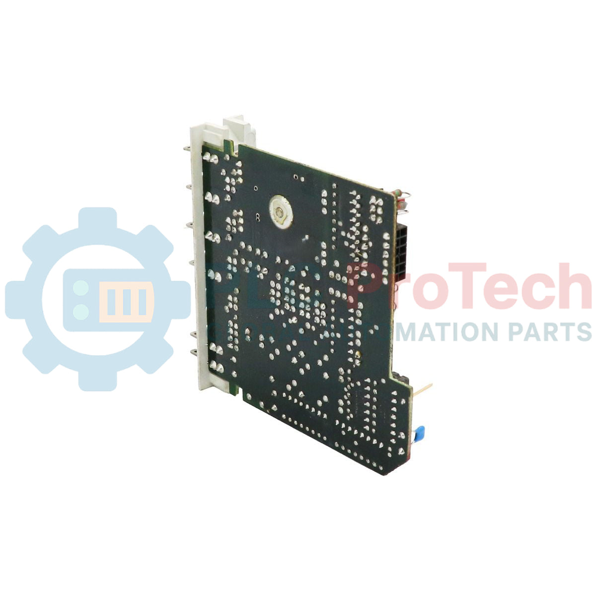
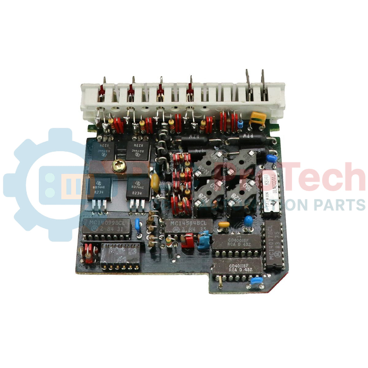
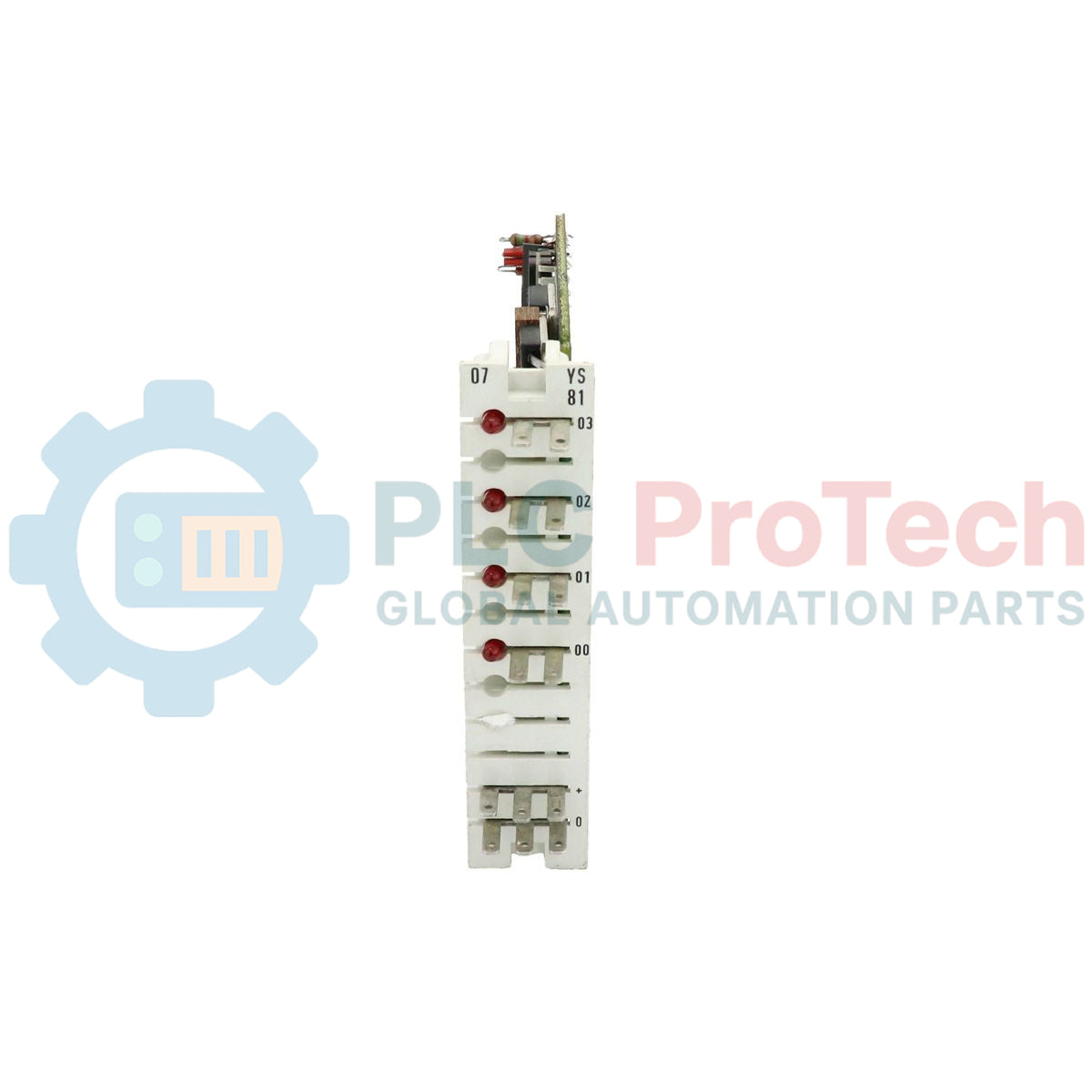
Designed to expand the switching capacity of legacy industrial control systems, the ABB GJR5221800R1 (also designated as the 07YS81) is a high-reliability digital output module within the legacy Advant Controller 31 (AC31) and PROCONTIC automation architectures. This module processes binary control signals from the central processing unit and translates them into discrete field-level actuation commands, facilitating robust interfacing with solenoids, contactors, indicators, and auxiliary relays in demanding operational environments.
Features
- Seamless integration into the legacy ABB Advant Controller 31 system architecture.
- Robust discrete switching design tailored for industrial electrical environments.
- Clear front-panel LED diagnostics for rapid channel status monitoring and fault isolation.
- Compact DIN-rail mountable form factor for high-density control cabinet configurations.
- Interoperability with standard PROCONTIC-series communication buses.
Applications
- Legacy factory automation and assembly line machinery control.
- Process control systems requiring discrete digital signal routing.
- Power distribution monitoring and medium-voltage substation signaling.
- Water and wastewater plant control panel modernization and maintenance.
Technical Specifications Table
| Parameter |
Specification |
| Manufacturer |
ABB |
| Model Designation |
GJR5221800R1 / 07YS81 |
| Product Series |
Advant Controller 31 (PROCONTIC) |
| Module Type |
Digital Output Module |
| Commodity Code |
85389091 |
| System Bus Protocol |
CS31 System Bus Compatibility |
| PLM Lifecycle Phase |
Phase-Out (Classic/Legacy Support) |
| Shipping Weight (Calculated) |
0.50 kg |
| Package Dimensions (Calculated) |
25.0 x 12.0 x 10.0 cm |
Alternative Models & Compatibility
The GJR5221800R1 functions as a direct spare and replacement for existing 07YS81 PROCONTIC modules. When retrofitting or replacing units within legacy AC31 systems, ensure that your existing central master unit firmware is fully compatible with this specific hardware revision. This module communicates over the proprietary CS31 fieldbus network; always verify terminal addressing switches on the unit are configured to match the original application program before powering the system.
Application Pitfalls & Engineering Notes
To ensure reliable continuous operation of legacy digital outputs, avoid routing logic-level and high-power load lines within the same wiring duct. Inductive transients from solenoids or large contactor coils can cause signal interference on the internal electronics. Additionally, legacy modules are sensitive to extreme thermal environments; ensure control enclosures do not exceed 55 Celsius (degC) ambient temperature to prevent thermal stress on the discrete output driver components.
Commissioning & Wiring Tips
When wiring discrete field devices to the module, ensure proper loop fusing and polarity matching of the auxiliary DC process supply voltage. High inductive switching spikes must be suppressed directly at the source using freewheeling diodes (for DC circuits) or RC snubbers (for AC circuits). To guarantee robust communication over the CS31 system bus, use shielded twisted-pair cabling and ensure that the shield is grounded at a single, low-impedance master point.
Installation Guidelines
CRITICAL WARNING
Before performing any physical installation, wiring, or maintenance on this module, verify that all primary power supplies to the host PLC rack and auxiliary field loops are completely de-energized. Failure to isolate power can result in system bus corruption, equipment destruction, or severe electric shock.
1
Mount the module securely on a standard 35mm symmetrical DIN rail, ensuring the locking latch fully engages to provide proper physical support and grounding connectivity.
2
Configure the hardware-based address switches on the front or side of the module to align with the correct slot assignment or network address defined in your system controller software configuration.
3
Wire the field output lines and the system bus lines to their respective terminals, observing exact polarities and ensuring all terminal screws are torqued to manufacturer specifications.