Description
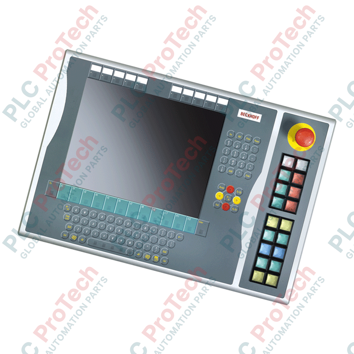
Designed to expand the manual operator control interface of modern industrial workstations, the Beckhoff C9900-E675 provides physical command execution directly adjacent to CP6xxx and CP7xxx control panels. This robust hardware extension is specifically sized and engineered to mount on the right side of control systems utilizing a 15-inch display paired with an alphanumeric keyboard layout, including the CP6x32-00xx and CP7x32-00xx series. Operating in its service phase, this module ensures reliable physical input channels to supplement touchscreen and keyboard operations in demanding industrial environments.
Features
-
Right-Side Panel Integration: Directly mounts and aligns with the right-side profile of 15-inch Beckhoff Control Panels and Panel PCs.
-
Industrial Actuators: Equipped with 18 square (30 x 30 mm) Siemens Signum push-button keys integrated with individual signal lamps.
-
Dedicated Safety Path: Includes 1 heavy-duty Siemens Signum emergency stop button designed for direct, hardwired connection to safety control systems.
-
Custom Labeling Options: Push-button caps are designed to accept custom labeling inserts for clear, site-specific function identification.
-
Dual-Channel Transmission Schema: Primary control transmission is processed via CP-Link or USB (normally-open contact mapping), while a secondary terminal row allows direct hardwired execution of a second normally-open contact.
-
Monitored Signal Lamps: All integrated status lamps are driven via the digital CP-Link or USB interface.
Applications
-
Heavy CNC & Machining Centers: Provides immediate tactile overrides for axis manipulation, spindle control, and coolant commands.
-
Automated Production Lines: Enables localized, high-reliability manual operation next to visual HMI screens.
-
Safety-Critical Cells: Separates standard operator control pathways from direct safety wiring (such as emergency stop circuits).
Technical Specifications Table
| Parameter |
Specification |
| Manufacturer |
Beckhoff Automation |
| Model Number |
C9900-E675 |
| Compatibility |
CP6x32-00xx and CP7x32-00xx (15-inch display models with alphanumeric keyboard) |
| Push-Button Configuration |
18x Push-buttons with feedback signal lamps |
| Emergency Stop |
1x Siemens Signum Emergency Stop (directly wireable) |
| Button Mechanical Size |
30 x 30 mm (Square) |
| Transmission Interfaces |
CP-Link or USB, plus independent hardwired terminal row |
| Signal Lamp Control |
CP-Link / USB only |
| Contact Configuration |
Dual Normally-Open (N.O.) contacts per push-button |
| Lifecycle Phase |
Service Phase (Legacy support and spare parts availability) |
| Country of Origin |
Germany |
| Shipping Weight (Calculated) |
5.0 kg |
Connections and Interfaces
| Connection Point |
Function / Circuit Assignment |
| CP-Link / USB Interface |
Data transmission path for Primary Contact (1st N.O.) and power/signal commands for all integrated status lamps. |
| Terminal Row (Internal) |
Direct copper termination for Secondary Contact (2nd N.O.) per button, bypassing active USB/CP-Link electronics. |
| Emergency Stop Terminals |
Isolated, direct-wired terminal connection dedicated to safety relay loop insertion. |
Empirical Engineering Insights
Alternative Models & Compatibility
Because this extension module is in its service phase, physical replacements must precisely match the host panel display size. The C9900-E675 is specifically dimensioned for 15-inch displays with alphanumeric keyboards. Swapping with modules designed for alternative display sizes (e.g., 12-inch or 19-inch variants) will result in physical mounting misalignment and mechanical stress on the housing seals.
Application Pitfalls & Engineering Notes
While standard button closures are communicated efficiently via CP-Link or USB, communication latency can occur under heavy PLC bus loading or operating system interrupts. Consequently, critical interlocks, active machine movement overrides, and safety circuits must utilize the secondary, direct-wired terminal row rather than relying solely on the USB/CP-Link data path.
Commissioning & Wiring Tips
During initial installation, ensure that the internal cabling for the direct-wired terminal block is routed with sufficient slack to prevent strain when opening or servicing the control panel assembly. Use shielded, twisted-pair cabling for all direct-wired signals to maintain high electromagnetic compatibility (EMC) in high-noise environments near variable frequency drives.
Installation Guidelines
CRITICAL WARNING: Isolate and de-energize all power sources feeding the Control Panel and the associated control cabinet before initiating physical installation. Confirm that all residual electrical charge has completely dissipated. Failure to follow proper lock-out/tag-out (LOTO) procedures can result in severe equipment damage or electrical shock.
1
Align the C9900-E675 housing with the mounting channels located on the right side of the CP6x32 or CP7x32 Control Panel.
2
Secure the mechanical connection using the provided fastening screws, ensuring a flush fit to maintain the ingress protection rating of the assembly.
3
Route and connect the internal USB or CP-Link connector to the matching header on the mainboard of the Control Panel.
4
Terminate the hardwired emergency stop safety loop and auxiliary terminal row connections back to the corresponding safety PLC or terminal block distribution inside the main control cabinet.
5
Reapply power, perform local signal loop checks on all 18 buttons and lamps, and execute a functional safety test of the emergency stop circuit before putting the system into active operation.