Description
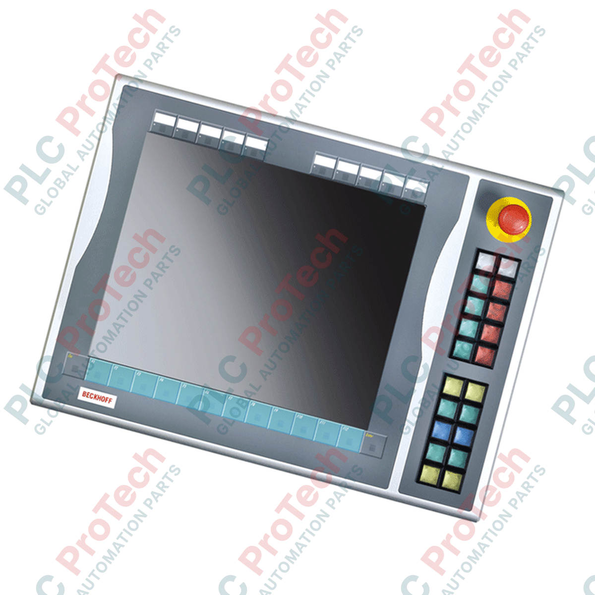
Providing tactile, hardware-level operator interaction, the Beckhoff C9900-E738 serves as a right-side mounted push-button extension engineered specifically for 15-inch CP6xxx and CP7xxx Control Panels and Panel PCs configured without integrated keyboards. This unit integrates physical manual controls directly alongside the visual interface, bridging industrial software visualization with hard-wired machine operation. It operates in the legacy service phase, serving as a critical direct-fit replacement part for existing industrial control setups.
Key Features
-
Ergonomic Layout: Outfitted with 20 square Siemens Signum push-buttons (30 x 30 mm) equipped with integrated signal lamps.
-
Dedicated Emergency Stop: Features 1 high-visibility Siemens Signum emergency stop key designed for independent safety loop routing.
-
Hybrid Signal Interface: Standard keystrokes and visual lamp signals transmit efficiently via USB, while a built-in terminal strip provides secondary, direct-wired, normally-open (NO) contacts for physical PLC interface options.
-
Insertable Labels: Slide-in labeling option allows on-site operators to define custom function markings for each button cap.
-
Rugged Enclosure Mounting: Built to lock directly onto the right-hand chassis profile of 15-inch Beckhoff operator interfaces.
Industrial Applications
- Automotive assembly lines utilizing CP6x13-00xx and CP7x13-00xx HMI screens.
- Metalworking machinery requiring secondary hard-wired validation paths alongside digital control signals.
- Material handling systems and distribution plants requiring high-durability physical start, stop, and emergency override switches.
Technical Specifications
| Parameter |
Value / Rating |
| Manufacturer |
Beckhoff Automation GmbH & Co. KG |
| Model Reference |
C9900-E738 |
| Compatible Panels |
CP6x13-00xx, CP7x13-00xx (15-inch displays without keyboard) |
| Mounting Location |
Right side |
| Push-Button Type |
20x Siemens Signum square (30 x 30 mm) |
| Emergency Stop |
1x Siemens Signum, direct hard-wired routing supported |
| Keystroke Transmission |
USB (1st NO contact) + Terminal Block (2nd NO contact) |
| Signal Lamp Transmission |
USB transmission interface only |
| Lifecycle Phase |
Service Phase (Legacy Replacement Availability) |
| Country of Origin |
Germany |
| Shipping Weight (Calculated) |
5.0 kg |
Empirical Engineering Insights
Alternative Models & Compatibility
The C9900-E738 is specifically designed to match the physical height and mounting profile of 15-inch Beckhoff displays. When upgrading legacy displays to newer Multi-touch screens, check frame layout changes, as legacy physical extensions like the E738 will not fit the physical mounting tracks of modern C9900 series panels directly without adapter brackets.
Application Pitfalls & Engineering Notes
Because all signal lamps on this module operate strictly through the USB bus, critical visual safety statuses must not rely solely on these lamps. The safety-related status indications must instead be hard-wired to local indicators. Ensure your host operating system is configured to prevent USB selective suspend, which can cause keypress delays or failure to register signals.
Commissioning & Wiring Tips
To configure dual-channel safety loops, the primary NO contact can be monitored by the control PC via USB for functional sequencing, while the physical terminal row must be wired back directly to dedicated safety input modules (e.g., Beckhoff EL1904 EtherCAT Terminals) using shielded, twisted-pair cabling to prevent EMI issues inside high-vibration enclosures.
Installation Guidelines
CRITICAL WARNING: SAFETY COMPLIANCE REQUIRED
Isolate all electrical power sources driving the host Panel PC and safety relays before mechanical integration. Ensure the Emergency Stop circuit is independently validated using a functional safety test before commissioning the system for regular machine operation.
1
Align the guide pins on the C9900-E738 chassis with the mounting groove located on the right side of your 15-inch CP6xxx/CP7xxx panel.
2
Secure the extension module to the panel housing using the designated internal hex tension fasteners, ensuring uniform pressure to preserve IP protection ratings.
3
Route the integrated USB interface cable to an unused host-side port on the control PC or active hub.
4
Wire the secondary Emergency Stop contact loop from the rear terminal strip directly into your hard-wired physical emergency chain.