Description
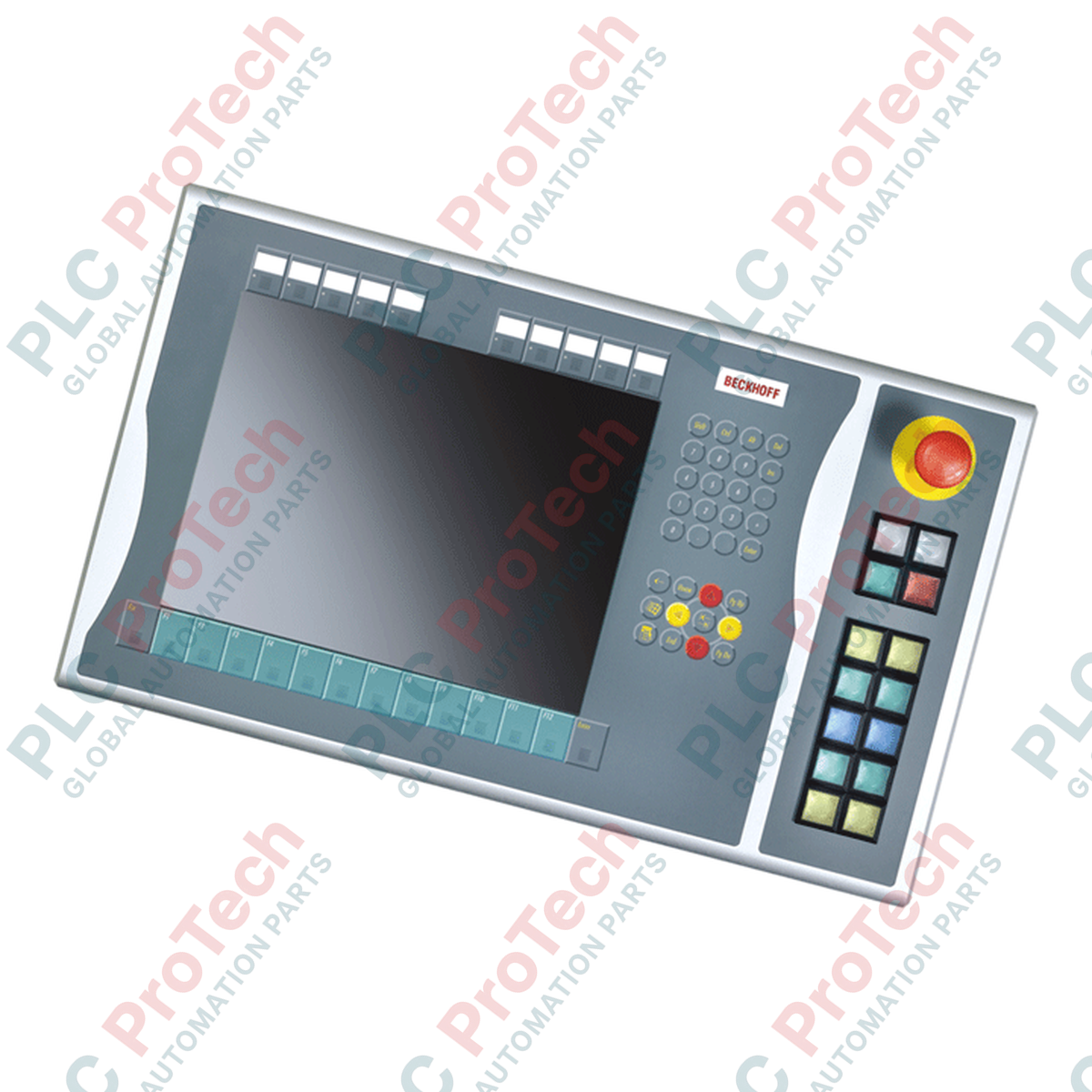
Designed to expand physical operator interfaces on machine-level HMI installations, the BECKHOFF C9900-E768 provides external tactile controls mounted directly on the right side of compatible industrial displays. Built specifically for 15-inch CP6x22-00xx and CP7x22-00xx Control Panels and Panel PCs operating without integrated keyboards, this auxiliary module adds heavy-duty physical control keys while maintaining structural integration. It is an optimal hardware solution for applications transitioning through the manufacturer's active service phase, ensuring legacy systems maintain tactile controls. The integration of Siemens Signum square hardware and dual-path connection mechanisms delivers rugged and reliable performance in demanding industrial environments.
Features
-
Right-Side Interface Extension: Seamlessly mounts onto the right frame of 15-inch Beckhoff display units.
-
Industrial Key Array: Features 14 Siemens Signum square (30 x 30 mm) push-buttons equipped with integrated signal lamps.
-
Dedicated Emergency Stop: Includes 1 high-visibility Siemens Signum emergency stop button designed for direct hardware safety circuit routing.
-
Dual Contact Functionality: Supports a primary normally-open (NO) contact routed over CP-Link or USB, alongside a secondary hardwired NO contact accessible via a terminal row.
-
Customizable Marking: Clear, insertable label caps allow rapid on-site labeling of individual button functions.
Applications
-
Automotive Assembly Lines: Integrated right-side controls for manual machine overrides and system restarts.
-
Process Plant Visualization: Hardwired E-stop and control interface expansion directly adjacent to the main screen.
-
Legacy Panel Maintenance: Direct drop-in component replacement for CP6x22 and CP7x22 installations requiring ongoing service lifecycle support.
Technical Specifications
| Parameter |
Specification |
| Manufacturer |
Beckhoff Automation GmbH & Co. KG |
| Article Number / SKU |
C9900-E768 |
| Compatible Displays |
15-inch CP6xxx and CP7xxx without built-in keyboard (specifically CP6x22-00xx and CP7x22-00xx) |
| Mounting Position |
Right-hand side of panel |
| Push-Button Type |
14 x Siemens Signum square, 30 x 30 mm |
| Emergency Stop Type |
1 x Siemens Signum, direct hardwire configuration |
| Key Signal Transmission |
USB or CP-Link (Contact 1) / Direct terminal strip (Contact 2) |
| Lamp Signal Transmission |
Exclusively via CP-Link or USB interface |
| Lifecycle Phase |
Service Phase (Legacy Support) |
| Shipping Weight |
5.0 kg (11.0 lbs) |
Connections and Interfaces
| Interface Path |
Function and Wiring Assignment |
| CP-Link / USB Bus Connection |
Transmits digital key state of Contact 1 for all 14 push-buttons; drives power to all integrated signal lamps. |
| Rear Terminal Strip |
Provides independent, hardwired access to the isolated Contact 2 (Normally Open) of each of the 14 push-buttons. |
| Emergency Stop Terminals |
Dedicated, fully-isolated terminal block for direct wiring of the E-stop switch into the plant's physical safety relay circuit. |
Empirical Engineering Insights
Alternative Models & Compatibility
This expansion panel is designed specifically for Beckhoff 15-inch displays. Attempting to fit this mechanical layout onto 12-inch or 19-inch variants will lead to misalignment of the chassis mating holes and failure of physical integration. For servicing older CP6x22 and CP7x22 variants, ensure the firmware revision of the host controller supports the dual-contact configuration over CP-Link if you intend to run control loops without auxiliary terminal-row wiring.
Application Pitfalls & Engineering Notes
A common design pitfall is attempting to hardwire the 14 integrated signal lamps. These lamps receive power and commands strictly through the USB/CP-Link bus connection. If the digital communication link is disrupted, the signal lamps will not function, even if the secondary NO contacts of the push-buttons remain functional via the hardwired terminal strip.
Commissioning & Wiring Tips
Always separate the hardwired digital input cabling connected to the secondary terminal row from high-voltage AC cables in the wire duct to prevent noise coupling on long runs. For high-vibration applications, verify that cable strain reliefs are anchored within the panel enclosure to prevent tension on the interface connector.
Installation Guidelines
CRITICAL WARNING: SAFETY COMPLIANCE REQUIRED
Isolate and lock out all electrical power supplying the Control Panel/Panel PC and all auxiliary terminal strip voltages before initiating the mechanical connection of the C9900-E768. The emergency stop circuit must undergo a full functional validation test before returning the machine to production.
1
Align the push-button extension housing with the pre-machined mounting points on the right-hand side of the 15-inch Control Panel.
2
Secure the mechanical assembly using the specified OEM fasteners, ensuring the integrated perimeter gasket forms a tight seal against dust and liquid ingress.
3
Connect the internal USB or CP-Link wiring harness to interface the button outputs and primary lamp controls with the panel's main logic board.
4
Wire the physical E-stop switch directly to your safety relay, and optionally terminate the redundant secondary NO contacts to your PLC's input modules via the integrated terminal strip.