Description
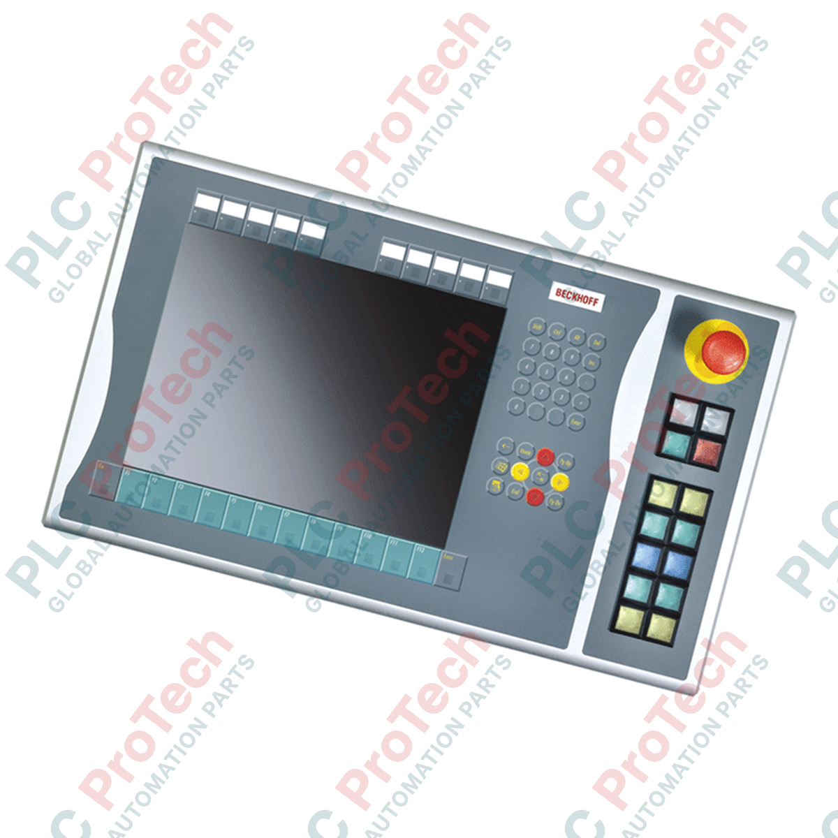
Facilitating robust physical human-machine interface interaction, the Beckhoff C9900-E805 mounts directly to the right side of CP6x21-00xx and CP7x21-00xx Control Panels and Panel PCs with 15-inch displays. This push-button extension provides operators with tactile physical controls alongside the touchscreen interface. Designed for environments requiring high mechanical feedback, the unit integrates twelve customizable square push-buttons and an integrated, directly wireable emergency stop device. By offering two parallel communication paths—integrated serial digital transmission via CP-Link or USB, alongside secondary direct-wiring physical terminals—this hardware extension ensures critical machine execution commands remain highly reliable and deterministically wired back to safety controllers or PLC input cards.
Key Features
-
Optimized Form Factor: Engineered specifically for right-side mounting on 15-inch Beckhoff control units without built-in keyboards.
-
Industrial Control Elements: Equipped with 12 square 30 x 30 mm Siemens Signum push-button keys, each featuring integrated software-controlled signal lamps.
-
Dedicated Safety HMI: Includes 1 heavy-duty Siemens Signum emergency stop button, designed for direct hardwiring into safety-rated control circuits.
-
Dual-Channel Interface: Operates primarily over CP-Link or USB for command transmission and signal lamp control, paired with an auxiliary terminal block enabling physical hardwiring of a second normally-open contact for every button.
-
Customizable Legend Plates: Clear, slide-in labeling pockets allow localized and application-specific key marking.
Applications
- Automotive assembly line Operator Control Stations (OCS).
- Metalworking machinery and CNC tooling centers requiring physical Cycle Start/Feed Hold interaction.
- Packaging, sorting, and material handling systems requiring local visual indication and emergency isolation capability.
- Explosive or challenging production areas where wet-glove touch panel operation is supplemented by physical push-buttons.
Technical Specifications
| Parameter |
Specification Value |
| Manufacturer |
Beckhoff Automation |
| Model Reference |
C9900-E805 |
| Product Lifecycle Phase |
Service Phase (Legacy/Replacement Support) |
| Display Size Compatibility |
15-inch displays (without keyboard integrations) |
| Control Panel Models |
CP6x21-00xx, CP7x21-00xx Series |
| Push-Button Element type |
Siemens Signum, Square 30 x 30 mm |
| Total Configurable Keys |
12 Keys with integrated illumination |
| Emergency Stop Element |
1x Siemens Signum mechanical push-lock turn-reset button |
| Communication Protocol |
CP-Link or USB (for primary key state transmission and LED control) |
| Parallel Contact Interface |
Terminal strip for direct point-to-point hardwiring (second NO contact) |
| Emergency Stop Interface |
Direct hardwired connection (independent of serial bus) |
| Country of Origin |
Germany |
| Shipping Weight (Calculated) |
5.00 kg |
Connections and Interfaces
| Interface Location |
Interface Type |
Functional Assignment |
| Internal Bus Port |
CP-Link / USB Connector |
Main interface backplane connection to host Control Panel logic board for key states and LED control. |
| Rear Access Terminal Strip |
Screw Clamp/Push-In Terminal Row |
Direct physical access to secondary normally-open (NO) contacts for customized safety or legacy PLC wiring. |
| E-Stop Dedicated Terminal |
Independent Terminal Block |
Isolated dual-contact routing directly to safety monitoring relays or fail-safe inputs. |
Empirical Engineering Insights
Alternative Models & Compatibility
The C9900-E805 unit is tailored strictly for 15-inch Control Panels. It cannot be retrofitted to smaller (e.g., 12-inch) or larger (e.g., 19-inch) display housings due to structural mounting spacing and cable harnesses. Since this is in its Service Phase, existing systems running CP6x21 or CP7x21 hardware should maintain a backup spare of this model. If transitioning to newer CP2xxx or CP3xxx panels, a different generation of push-button extensions is required, as the electrical interface signals differ.
Application Pitfalls & Engineering Notes
While the push-buttons are transmitted digitally via CP-Link or USB under normal operation, never rely on the USB or CP-Link serial communication pathway for emergency isolation. The emergency stop button must always be hardwired directly from its rear contacts to safety-rated safety relays (such as EL6900 or dedicated safety modules) to meet SIL 3/Category 4 safety directives.
Commissioning & Wiring Tips
When configuring the auxiliary terminal rows for dry contact wiring, ensure control wiring does not run parallel to high-voltage, high-frequency motor cables to prevent EMI. Grounding the frame of the associated CP6xxx/CP7xxx panel via the ground stud is mandatory for the internal digital encoders to operate reliably without signal dropouts.
Installation Guidelines
CRITICAL SAFETY WARNING
Isolate and de-energize all power sources feed to the primary Control Panel or Panel PC and auxiliary terminal strip connections before mechanical integration. Ensure the field bus line is inactive. Discharge electrostatic buildup by grounding yourself to the machine frame before making connections to the internal components.
1
Affix the mechanical brackets supplied with the C9900-E805 extension to the side bezel of the compatible 15-inch Beckhoff Control Panel. Ensure the seal profiles are properly seated.
2
Route the internal USB or CP-Link data harness into the panel chassis, connecting it firmly to the designated logic board header socket.
3
Hardwire the emergency stop dual-channel contacts to your local safety logic loop via the terminal row block. Use shielded, twisted-pair wire.
4
If auxiliary discrete physical feedback is required, wire the secondary terminal block lines to your PLC digital input modules. Tighten terminal screws according to specifications.
5
Reassemble panel enclosure seals, mount the panel housing, re-apply circuit power, and perform functional tests of all illuminated elements and physical transitions.