Description
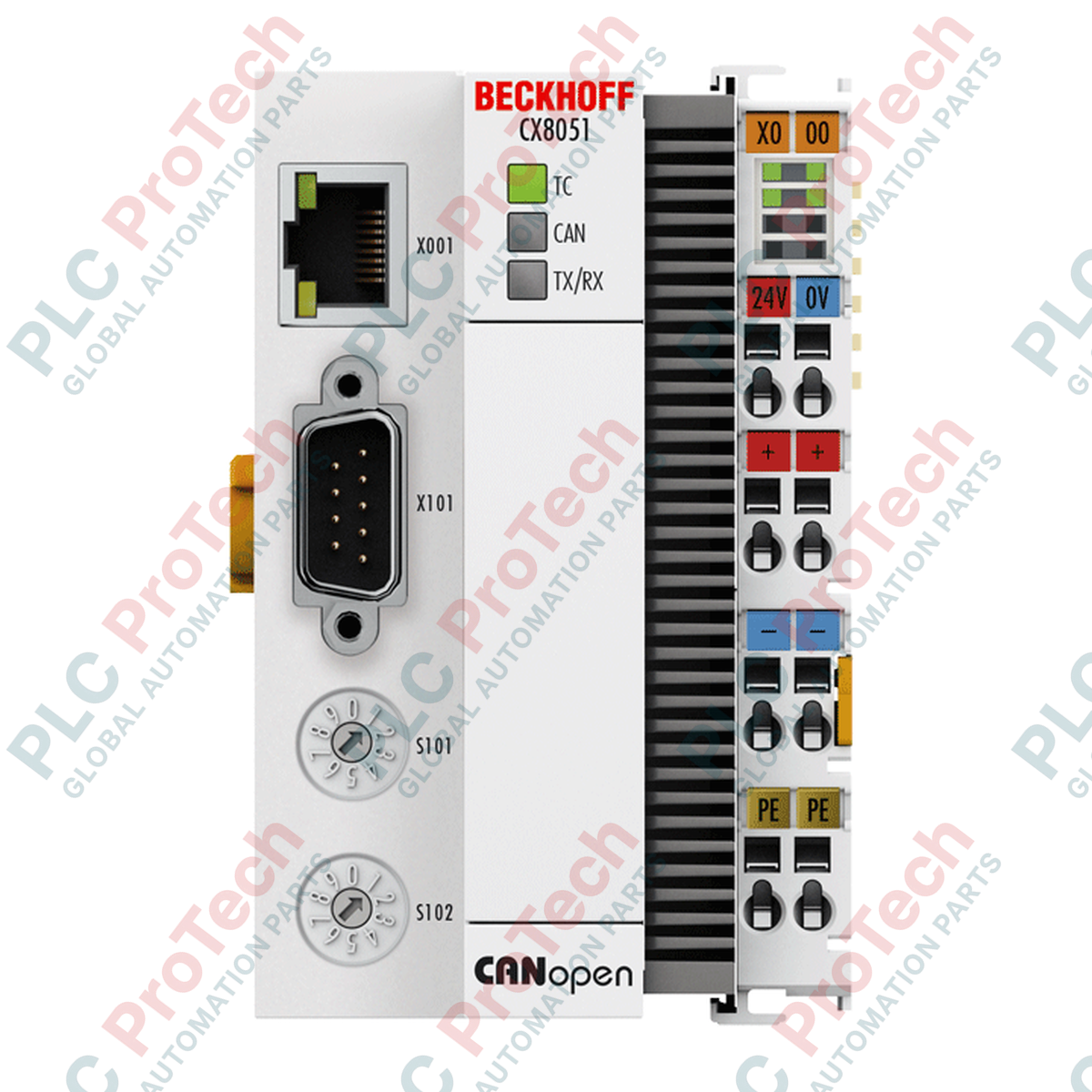
Designed as a compact, fieldbus-capable control system, the Beckhoff CX8051 integrates an ARM9 processor to execute local PLC tasks while operating natively as a high-performance CANopen slave interface. This embedded controller combines the versatility of industrial PC technology with traditional fieldbus systems, enabling modular I/O integration within a DIN rail mountable form factor. Driven by the TwinCAT 2 runtime environment and Windows Embedded CE 6 operating system, the unit manages local control loops while exchanging critical operational parameters with a master control system via its galvanically decoupled D-sub interface.
Features
- ARM9 400 MHz processing core provides reliable deterministic control for small-to-medium industrial systems.
- Integrated 1-second capacitive UPS retains up to 1 MB of persistent variables during unplanned power loss.
- Automatic physical recognition and support for both EtherCAT (E-bus) and Bus Terminals (K-bus).
- Galvanically decoupled 9-pin D-sub connection adhering strictly to CANopen communication specifications.
- Dedicated diagnostic LEDs indicating TwinCAT operational states and fieldbus communication statuses.
Applications
- Distributed I/O processing and subsystem control within large CANopen industrial networks.
- Infrastructure and building automation system integration utilizing TwinCAT 2 programming.
- Hazardous industrial processes requiring compliance with ATEX, IECEx, and cFMus Class I Division 2 safety norms.
Technical Specifications
| Parameter |
Specification Value |
| Manufacturer |
Beckhoff Automation |
| Model Number |
CX8051 |
| Processor |
ARM9, 400 MHz (Single Core) |
| Flash Memory |
512 MB microSD (expandable via industrial-grade cards) |
| Main Memory |
64 MB DDR2 RAM (non-expandable) |
| Persistent Memory |
1-second UPS (1 MB persistent data capacity) |
| Operating System |
Windows Embedded CE 6 |
| Control Software |
TwinCAT 2 PLC Runtime |
| Interfaces |
1 x RJ45 (10/100 Mbit/s), 1 x USB Device (under front flap), 1 x CANopen D-sub 9-pin |
| Supported I/O Bus |
E-bus (EtherCAT) or K-bus (Bus Terminals) with automatic detection |
| Bus Power Supply Current |
2.0 A maximum |
| Power Consumption |
3.0 W maximum |
| Dimensions (W x H x D) |
64 mm x 100 mm x 73 mm |
| Net Weight |
180 g |
| Shipping Weight (Calculated) |
0.5 kg (inclusive of industrial packaging) |
| Operating Temperature |
0 degC to +55 degC |
| Storage Temperature |
-25 degC to +85 degC |
| Relative Humidity |
95% non-condensing |
| Protection Rating |
IP20 |
| Ex Markings (ATEX) |
II 3 G Ex nA IIC T4 Gc, II 3 D Ex tc IIIC T135 degC Dc |
Connections and Interfaces
| D-sub 9-Pin Connector |
CANopen Signal Assignment |
| Pin 2 |
CAN_L (Dominant Low bus line) |
| Pin 3 |
CAN_GND (Ground reference) |
| Pin 7 |
CAN_H (Dominant High bus line) |
| Pin 1, 4, 5, 6, 8, 9 |
Not connected / Reserved |
Empirical Engineering Insights
Alternative Models & Compatibility
The CX8051 represents a dedicated fieldbus-dependent controller within the CX80xx series family. While models like the CX8090 handle Ethernet/IP or Modbus TCP communication, the CX8051 cannot be converted to support alternative fieldbuses via firmware modification, as the CANopen physical layer is hardwired to the main board. When upgrading older systems configured with TwinCAT 2, ensure target settings in the TwinCAT System Manager are locked to the ARM platform (ARMV4I) and check library dependencies prior to download.
Application Pitfalls & Engineering Notes
Always ensure adequate thermal clearance (at least 30 mm above and below the module) to maintain passive heat convection. Running the CX8051 in compact enclosures without structured ventilation can cause the unit to exceed its maximum operating limit of +55 degC, leading to CPU throttling or memory access faults. Furthermore, users must avoid writing frequent log cyclic parameters directly to the microSD card. Standard flash cells degrade quickly under rapid write patterns; utilize the persistent 1 MB UPS memory space for continuous variables, committing values to flash only during controlled shutdown cycles.
Commissioning & Wiring Tips
The CANopen address (Node ID) of the CX8051 can be hardcoded via physical address switches located behind the front flap or directly configured through TwinCAT software settings. For trouble-free bus communication, a 120-Ohm termination resistor must be connected across Pin 2 (CAN_L) and Pin 7 (CAN_H) at both physical ends of the CAN bus network. Keep signal cables isolated from high-voltage motor lines to prevent electromagnetic interference from disrupting the galvanically decoupled communication circuitry.
Installation Guidelines
CRITICAL WARNING
Disconnect all operational electrical supplies before installing, wiring, or removing the CX8051 module. Failure to de-energize primary and fieldbus circuitry can lead to terminal damage, signal interference on active communication nodes, or unexpected machinery startup.
-
1
Mount the CX8051 controller onto a standard 35 mm DIN rail (EN 60715) by aligning the top clip with the rail and pressing downward until the latching mechanism snaps firmly.
-
2
Align the adjacent EtherCAT (E-bus) or Bus Terminal (K-bus) slices and slide them onto the DIN rail, ensuring the side-mounted contacts fully engage with the CX8051's lateral bus connector.
-
3
Connect the 24 V DC power supply to the main power terminal blocks on the device, taking care to observe correct polarity markings to avoid internal fuse trips.
-
4
Insert the 9-pin D-sub CANopen communication cable into the lower bus connector, securing the retention screws to maintain solid galvanic grounding.