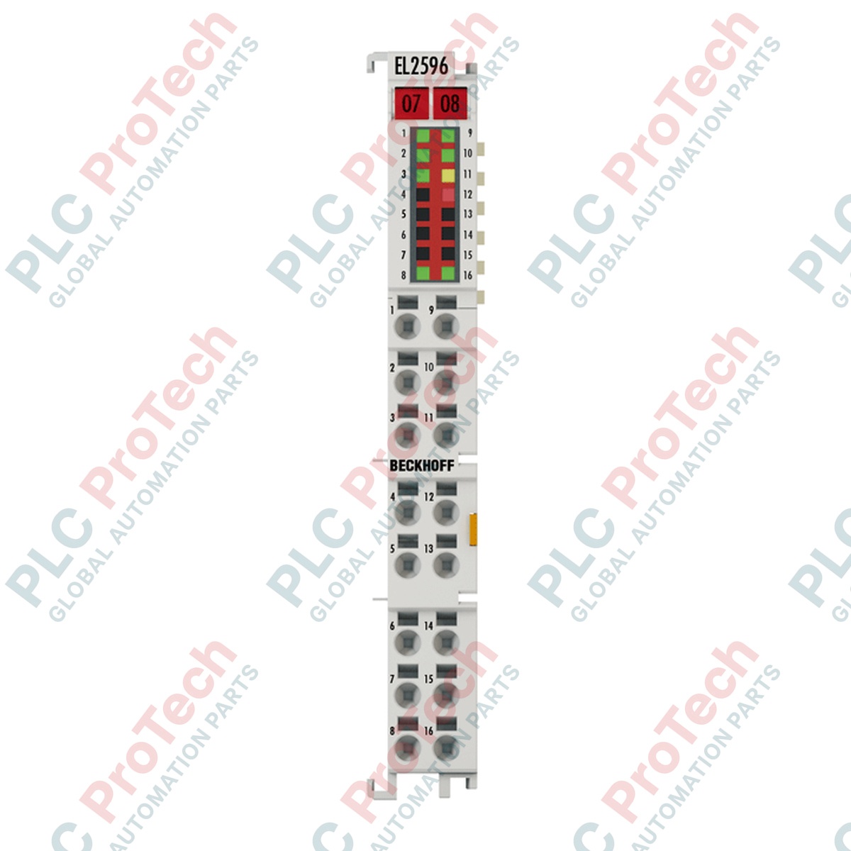
Description
Providing high-precision drive control for machine vision illumination systems, the Beckhoff EL2596 EtherCAT Terminal coordinates fast-switching LED outputs with sub-microsecond synchronization. This 1-channel LED output module operates on a 24 V DC system, offering adjustable output parameters across constant current, constant voltage, and pulse-width modulation (PWM) modes. By linking illumination triggers directly to the EtherCAT distributed clock system, the device facilitates micron-level coordination between industrial camera exposures and light strobes, ensuring optimal image capture consistency on high-speed automation lines.
Features
-
Multi-Mode Output Capability: Configurable support for constant voltage, constant current, and high-frequency PWM operating modes to match specific LED luminaire requirements.
-
Distributed Clock Synchronization: Highly precise timing synchronization with accuracy deviations well under 1 microsecond across the EtherCAT network.
-
Ultra-Fast Switching Times: Turn-on and turn-off times typified at less than 1 microsecond, supporting pulsed light intervals from 25 microseconds up to 10 seconds.
-
Isolated Camera Interfaces: Features one electrically isolated trigger input and one push-pull trigger output to interface seamlessly with industrial vision sensors and cameras.
-
Comprehensive Field Diagnostics: Real-time hardware status indicators and internal monitoring for current and voltage limits to prevent thermal damage to connected LEDs.
Applications
- Strobe and flash synchronization for industrial machine vision cameras.
- High-speed optical sorting and quality control inspection systems.
- Constant-current LED panel illumination and luminance management.
- Integrated RGB LED illumination setups via common-anode configurations.
Technical Specifications
| Parameter |
Specification Value |
| Manufacturer |
Beckhoff |
| Model Number |
EL2596 |
| Module Type |
EtherCAT Terminal (1-Channel LED Output) |
| Input Voltage |
24 V DC (-15% / +20%) |
| Load Type |
LED (Ohmic) |
| Output Current (Pulsed Mode) |
0 to 3 A (duty-cycle dependent) |
| Output Current (Continuous Mode) |
0 to 1.2 A |
| Distributed Clocks (DC) |
Yes (precision < 1 microsecond) |
| Switching Times (TON / TOFF) |
Typical < 1 microsecond |
| E-bus Current Consumption |
Typical 240 mA |
| Electrical Isolation |
500 V (E-bus / field potential) |
| Trigger Input |
1 isolated, typical 3 mA, 4 to 24 V DC |
| Trigger Output |
1 isolated, max 10 mA push-pull, 10 to 24 V DC |
| Housing Form Factor |
High Density (HD) with signal LEDs |
| Operating Temperature |
0 to +55 degC |
| Storage Temperature |
-25 to +85 degC |
| Dimensions (W x H x D) |
12 mm x 100 mm x 68 mm |
| Net Weight |
55 g |
| Shipping Weight (Calculated) |
0.15 kg |
Empirical Engineering Insights
Alternative Models & Compatibility
The EL2596 integrates seamlessly into standard Beckhoff TwinCAT 2 and TwinCAT 3 development environments. Ensure your TwinCAT EtherCAT XML device description (ESI) is updated to the latest revision to access all advanced CoE (CANopen over EtherCAT) parameters. It is backwards-compatible with standard EtherCAT couplers such as the EK1100.
Application Pitfalls & Engineering Notes
When configuring the terminal for pulsed operation up to 3 A, carefully manage the Duty Cycle settings within the control logic. Operating at high duty cycles under maximum current load can cause thermal buildup. It is highly recommended to mount the module vertically with adequate clearance above and below the terminal block to maintain passive airflow.
Commissioning & Wiring Tips
For sub-microsecond strobe timing, ensure that the cables feeding both the LED array and the camera trigger lines are properly shielded. Route low-voltage signal cables away from AC power lines or high-frequency motor drive cables to eliminate potential EMI noise coupling onto the fast trigger output line.
Installation Guidelines
CRITICAL WARNING
Isolate all electrical power sources from the EtherCAT system and the field supply bus before mounting or removing the EL2596 terminal. Failure to completely de-energize the assembly may lead to optical system damage or back-plane communication errors on the E-bus.
1
Align the terminal with the 35 mm DIN rail (conforming to EN 60715) and slide it firmly onto the rail until the locking mechanism clicks into place.
2
Ensure the lateral tongue-and-groove joint is properly aligned and engaged with any adjacent EtherCAT terminals to establish clean E-bus contact connection.
3
Strip terminal wires to 8–9 mm. Insert a standard screwdriver into the clamp release port to actuate the spring-cage, insert the solid or ferruled conductor, and release the clamp to secure the contact.