Description
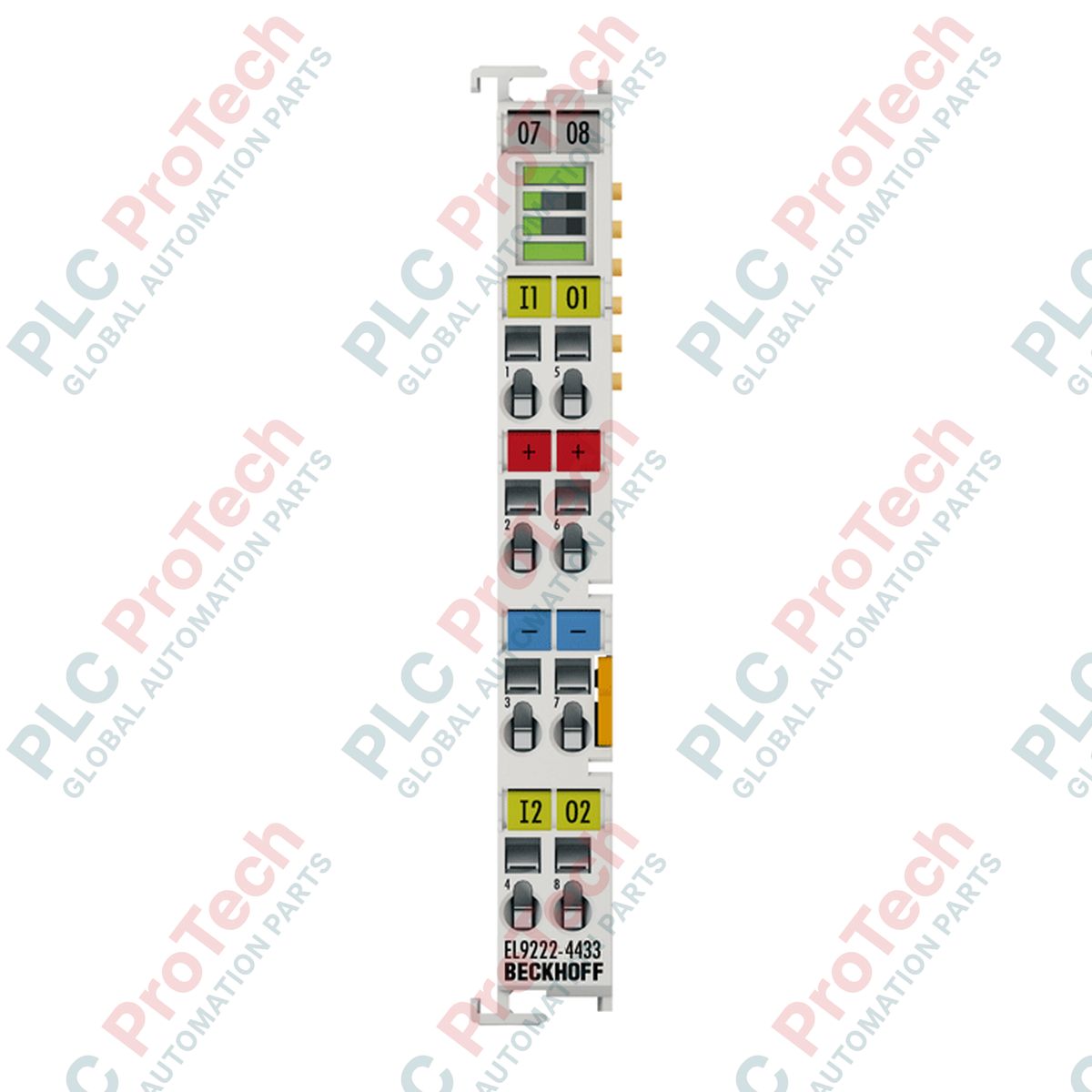
Designed to safeguard critical 24 V DC control circuits within EtherCAT industrial networks, the Beckhoff EL9222-4433 provides precise electronic overcurrent protection for dual channels rated at 3 A each. Operating directly within the standard EtherCAT terminal segment, this module dynamically monitors load currents, offering rapid electronic shutdown in the event of an overload or short circuit, thereby limiting system downtime. It features integrated status LEDs and physical push-buttons on the housing for immediate channel-level diagnostics and manual reset capability, while feeding complete diagnostic telemetry back to the controller via the E-bus interface.
Features
-
Dual-Channel Monitoring: Two independent 24 V DC distribution paths, limiting maximum current to 3 A per channel.
-
Hardware Redundancy: Integrated 4 A slow-blow fail-safe backup fuses provide hardware-level backup protection.
-
E-Bus Telemetry: Seamless configuration, current monitoring, and diagnostic reporting directly through TwinCAT.
-
Local Interactivity: Dedicated LED push-buttons on the terminal face allow for direct manual reset and instant physical status feedback.
-
High Packing Density: Compact 12 mm modular housing width minimizes DIN-rail footprint in control panels.
Applications
-
Sensor/Actuator Power Distribution: Safe current-limited supply routing for decentralized field sensors and valve terminals.
-
Control Cabinet Sub-Circuit Protection: Isolation of critical low-voltage hardware to prevent system-wide voltage collapses during single-point field faults.
-
EtherCAT Segment Protection: Protection of downstream auxiliary power contacts across I/O nodes.
Technical Specifications
| Parameter |
Specification |
| Manufacturer |
Beckhoff |
| Model / Article Number |
EL9222-4433 |
| Nominal Operating Voltage |
24 V DC |
| Number of Channels |
2 |
| Rated Current |
3 A per channel |
| Max. Input Supply Current |
10 A |
| Current Consumption (E-bus) |
80 mA typical |
| Electrical Isolation |
500 V (E-bus to signal voltage) |
| Backup Fail-Safe Element |
4 A slow-blow (T) / 4 A slow-blow (T) |
| Overvoltage Cut-off |
>= 32 V DC |
| Hold After Trip-Out |
>= 10 s |
| Advance Load Warning Threshold |
90 percent of rated channel load |
| Operating Temperature |
0 to 55 degC |
| Storage Temperature |
-25 to 85 degC |
| Enclosure Protection Rating |
IP20 |
| Housing Material |
Polycarbonate |
| Physical Dimensions (W x H x D) |
12 mm x 100 mm x 68 mm |
| Net Weight |
55 g |
| Shipping Weight (Calculated) |
2.0 kg |
| Certifications and Approvals |
CE, cULus, cURus |
Connections & Interface Terminal Guide
| Terminal Contact |
Wiring Specifications & Signal Mapping |
| Solid Conductor Range |
0.08 to 2.5 mm² (AWG 28 to 14) via screwdriver spring actuation |
| Stranded Conductor Range |
0.08 to 2.5 mm² (AWG 28 to 14) |
| Conductor with Ferrule (f) |
0.14 to 1.5 mm² (AWG 26 to 16) |
| Stripping Depth |
8 to 9 mm |
| Power Contact Rating |
Imax: 10 A (Output 1 utilizes internal power contact path) |
Empirical Engineering Insights
Alternative Models & Compatibility
The EL9222-4433 is optimized for 3 A fixed current limits per channel. For variable current configurations, look to the adjustable EtherCAT terminals (such as the EL9224). When inserting this module into an existing I/O stack, ensure that your TwinCAT EtherCAT XML Device Description (ESI) files are updated to match the specific firmware revision. If replacing an older EL9222-0000, verify that your E-bus current budget can handle the 80 mA load of the EL9222-4433.
Application Pitfalls & Engineering Notes
The absolute maximum capacity of the power contact rail is 10 A. Continuous heavy loads across multiple downstream modules must be calculated to prevent overload of the power contacts. If your segment exceeds 10 A total, you must insert an EL9100 or EL9110 power feed terminal directly upstream to segment the power contacts and prevent local terminal overheating.
Commissioning & Wiring Tips
To avoid intermittent faults, adhere strictly to the 8 to 9 mm stripping length. Under-stripping causes insecure mechanical tension clamp engagement, while over-stripping risks exposing bare wire to adjacent, closely-spaced terminals. When commissioning from TwinCAT, remember to map the CoE (CanOverEtherCAT) objects to read historical trip data and clear fault states remotely.
Installation Guidelines
CRITICAL WARNING:
De-energize the entire segment and isolate all 24 V DC power feeds before installing or removing the overcurrent protection terminal. Failure to do so may damage the E-bus connection pins, disrupt network communications, or lead to accidental arc discharges across adjacent contacts.
1
Align the EL9222-4433 terminal with the 35 mm DIN rail (conforming to EN 60715) alongside the existing EtherCAT segment. Ensure the slot and key guides line up correctly.
2
Press the terminal firmly onto the DIN rail until you hear the locking latch snap into position, securing the E-bus connections.
3
Using a standard terminal screwdriver, actuate the spring-actuated clamp connections to insert conductors stripped to 8-9 mm. Re-verify the wire cross-section conforms to AWG 28-14 (solid/stranded) or AWG 26-16 (ferrule).
4
Apply 24 V DC control power, boot the TwinCAT system, and verify that the front status LEDs illuminate green, indicating normal channel conditions.