Description
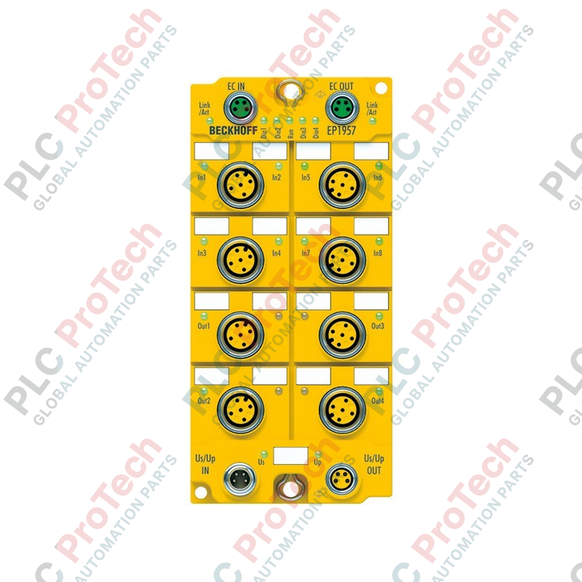
Serving as a direct, rugged link between safe input and output field signals, the Beckhoff EP1957-0022 enables decentralized safety logic execution within automated machinery. This IP67-rated TwinSAFE EtherCAT Box integrates safety inputs, safety outputs, and a local programmable safety controller into a single, compact field device. By mounting directly on the machine outside of control cabinets, the Beckhoff EP1957-0022 minimizes field-wiring complexity while maintaining compliance with strict global machine safety directives.
Features
-
Integrated Safety Logic: Supports localized safety PLC program execution via Safety over EtherCAT (FSoE).
-
IP67 Protection: Dust-tight and water-resistant enclosure engineered for direct machine mounting without an enclosure.
-
Flexible Signal Count: Equipped with 8 safe inputs and 4 safe outputs to manage local safety loops.
-
M12 Connection Technology: Uses standardized M12 5-pin, A-coded connection terminals for secure sensor/actuator integration.
-
Optimized Form Factor: Dual M8 shielded interfaces for deterministic, high-speed EtherCAT communication.
Applications
- Decentralized safety monitoring in packaging machinery and material handling systems.
- Robotic work cells requiring localized emergency stop, light curtain, and safety gate integration.
- Harsh industrial environments subject to washdown procedures, oil exposure, or fine particulate accumulation.
- Modular machine configurations where safety zones must operate independently or exchange safe status via FSoE.
Technical Specifications
| Parameter |
Specification |
| Manufacturer |
Beckhoff |
| Model Number |
EP1957-0022 |
| Protocol |
TwinSAFE / Safety over EtherCAT (FSoE) |
| Bus Interface |
2 x M8 socket, shielded, screw type |
| Connection Technology |
M12 x 1, 5-pin, A-coded |
| Number of Safe Inputs |
8 |
| Number of Safe Outputs |
4 |
| Max. Output Current |
0.5 A per channel |
| Cycle Time |
1 ms nominal (dependent on safety project size) |
| Fault Response Time |
<= parameterized watchdog time |
| Current Consumption (US) |
Max. 120 mA |
| Current Consumption (UP) |
Max. 60 mA |
| Protection Rating |
IP67 (conforms to EN 60529) |
| Safety Standards |
EN ISO 13849-1:2015 (Cat. 4, PL e), EN 61508:2010 (SIL 3) |
| Installation Position |
Variable / Multi-directional mounting |
| Unit Weight |
315 g |
| Shipping Weight (Calculated) |
2.0 kg |
Connections and Interfaces
| Connector Type |
Terminal Definition |
Functional Assignment |
| 2 x M8 Sockets |
EtherCAT In / Out |
Shielded, deterministic industrial communication path |
| M12 5-Pin (A-coded) |
Safe Inputs 1 to 8 |
Dual-channel or single-channel sensor input connections |
| M12 5-Pin (A-coded) |
Safe Outputs 1 to 4 |
0.5 A safe switching signals to actuators/contactors |
Empirical Engineering Insights
Alternative Models & Compatibility
The EP1957-0022 operates as a decentralized safety controller. If your architecture relies purely on centralized logic and only requires safety input expansions, consider the EP1908-0002. This module is compatible with TwinCAT 3.1 environments. Be aware that safety checksum modifications require a full download of the safety project via the EtherCAT master; on-the-fly logical modifications are restricted by safety standard requirements.
Application Pitfalls & Engineering Notes
While the safe outputs are rated for 0.5 A, inductive load switching requires external free-wheeling diodes if the internal suppression limits are exceeded during rapid cycles. Additionally, ensure the total current draw of the sensor supply (US) does not exceed 120 mA to prevent local overcurrent trips. When designing the physical layout, avoid mounting the device in direct proximity to high-vibration sources or extreme heat emitters without dynamic heat-sink spacing, as thermal buildup can reduce the operational life of the internal safety relays.
Commissioning & Wiring Tips
Always use high-quality, double-shielded M8 cabling for the EtherCAT network to avoid EMC-induced watchdog timeout errors, which automatically put the safety logic into a safe state. Ensure the metallic mounting brackets of the module are directly grounded to the machine frame to establish a low-impedance path for high-frequency noise. Verify that the US (sensor/control power) and UP (actuator peripheral power) circuits are fed from independent, certified Class 2 power supplies to maintain proper safety isolation.
Installation Guidelines
CRITICAL WARNING: ELECTRICAL SAFETY PROTOCOL
De-energize all primary, auxiliary, and safety-loop power distribution systems before physical installation or cable connection. Verify the complete absence of voltage across all terminals using a calibrated multimeter. Failure to isolate power can result in permanent damage to internal safety components, unexpected machine motion, or severe physical injury.
1
Securely mount the EtherCAT Box to a flat, vibration-damped surface using M4 screws, tightening them to a maximum torque of 1.2 Nm.
2
Attach the shielded M8 EtherCAT communication cables. Hand-tighten the connectors to ensure the IP67 sealing ring is properly compressed.
3
Connect the A-coded M12 cables for the safety inputs and safety outputs according to the safety loop schematic.
4
Verify that all unused M8 and M12 ports are sealed with approved IP67 protective caps to prevent dust and fluid ingress.
5
Apply power to the system, verify network connection status via the LED indicators, and execute a functional safety test of the logic project.