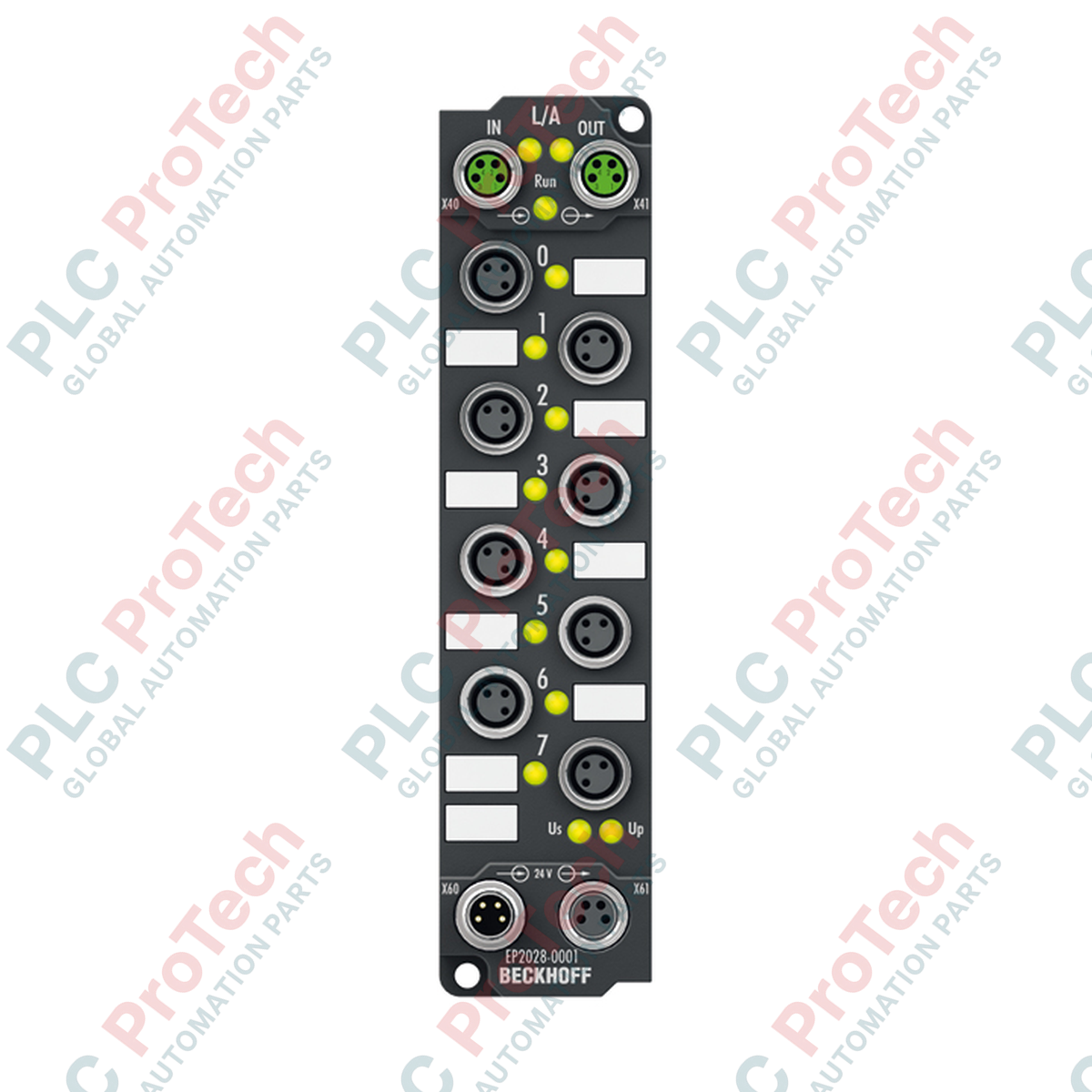
Description
Decentralized signal routing in demanding physical environments is optimized with the Beckhoff EP2028-0001 EtherCAT Box, an IP67-rated digital output module designed for mounting directly on machinery without control cabinets. This robust field device manages 8 digital outputs operating at 24 V DC, with each channel engineered to supply up to 2 A of load current. Featuring high-speed EtherCAT system integration, industrial M8 connection interfaces, and comprehensive electrical isolation, it delivers reliable output control for ohmic, inductive, and lamp loads under aggressive physical stress.
Features
-
High Current Output Capacity: Supplies up to 2 A per channel, allowing direct control of heavy actuator loads.
-
Individual Short-Circuit Protection: Each channel is isolated and short-circuit proof, preventing localized faults from disrupting the entire system.
-
Industrial-Grade Sealing: Achieves IP65, IP66, and IP67 protection ratings, safeguarding inner electronics from moisture and particulate ingress.
-
Standardized M8 Connectivity: Utilizes robust M8 interfaces for both high-speed EtherCAT communications and system/peripheral power.
-
Hazardous Location Certification: ATEX Zone 2 approval permits deployment within explosive atmospheres.
Applications
- Pneumatic valve terminal control and decentralized manifold switching.
- Direct machine-mount actuator control in automated material handling systems.
- Automated packaging and washdown environments requiring localized, cabinet-free I/O.
- Process plants and chemical environments utilizing hazardous area (ATEX) regulations.
Technical Specifications
| Specification Parameter |
Technical Value |
| Manufacturer |
Beckhoff |
| Model Number |
EP2028-0001 |
| Series |
EtherCAT Box (EP) |
| Fieldbus Protocol |
EtherCAT |
| Number of Outputs |
8 digital outputs |
| Nominal Output Voltage |
24 V DC (-15 percent / +20 percent) |
| Max. Output Current |
2 A per channel (individually short-circuit proof); Sum max. 4 A |
| Short-Circuit Current Limit |
Typically 15 A |
| Switching Delay |
TON: 200 us (typical); TOFF: 200 us (typical) |
| System Power Consumption (US) |
120 mA from US |
| Auxiliary Power Current (UP) |
20 mA typical + load current |
| Electrical Isolation |
500 V (system/auxiliary power to control logic) |
| Operating Temperature Range |
-25 to +60 degC |
| Storage Temperature Range |
-40 to +85 degC |
| Protection Rating |
IP65 / IP66 / IP67 (conforms to EN 60529) |
| Ex Marking |
II 3 G Ex nA IIC T4 Gc |
| Approvals |
CE, UL, ATEX |
| Unit Weight |
Approx. 165 g |
Connections and Interfaces
| Interface Type |
Connector Style |
Assignment Function |
| EtherCAT Bus Input/Output |
2 x M8 socket, shielded, screw type |
Inbound and downstream EtherCAT network routing |
| Digital Outputs (0 to 7) |
8 x M8 socket, 3-pin, A-coded |
Pin 1: +24 V DC auxiliary out; Pin 3: GND; Pin 4: Output signal |
| Power Feed |
1 x M8 male socket, 4-pin |
24 V DC system power (US) and peripheral power (UP) |
| Downstream Power |
1 x M8 female socket, 4-pin |
Power distribution loop to subsequent EtherCAT Box units |
Empirical Engineering Insights
Alternative Models & Compatibility
When standardizing field wiring layouts, contrast the EP2028-0001 (utilizing compact M8 connectors) with the EP2028-0002 (designed with dual M12 connection ports). Direct interchangeability is straightforward via the EtherCAT configuration files (ESI), although physical wiring adaptations are required if substituting M8 connectors for M12 variants. Ensure your TwinCAT system manager configurations are aligned with the exact hardware suffix to maintain cyclic communication timing.
Application Pitfalls & Engineering Notes
A primary engineering constraint of this module is the 4 A aggregate current limit for all channels combined. While individual outputs can switch up to 2 A, simultaneous high-current operation across multiple channels must not exceed 4 A. Exceeding this collective thermal limit will trip system diagnostic flags and may trigger short-circuit protective mechanisms. Engineers must calculate duty cycles and load profiles during design to avoid nuisance thermal shut-offs in high-load actuator applications.
Commissioning & Wiring Tips
For industrial environments with heavy electromagnetic interference (EMI), ensure the metal mounting brackets of the EtherCAT Box are directly grounded to the machine frame. Use shielded M8 network cables and torque connections to the OEM specification (0.4 Nm) to guarantee IP67 sealing. All unused output or power ports must be fitted with screw-on protective IP67 plastic caps to prevent moisture condensation or particulate contamination from compromising the internal signal paths.
Installation Guidelines
CRITICAL WARNING
Isolate all electrical power sources (both control system US power and peripheral UP power) before mounting, routing cables, or plugging/unplugging connections on the module. Live insertions can damage sensitive solid-state switching elements and compromise communication bus performance.
1
Position and secure the EtherCAT box onto a flat, vibration-resistant machine frame using M3 or M4 screws. Avoid applying excessive torque to the mounting tabs.
2
Connect the incoming EtherCAT bus cable to the top-left M8 socket. Loop downstream EtherCAT segments via the adjacent output socket.
3
Terminate the 4-pin M8 auxiliary power feed (US/UP). Verify that polarity and voltage drops across long cable runs remain within specified operational limits.
4
Secure all M8 actuator leads onto ports 0 through 7. Hand-tighten all knurled locking nuts to secure the IP67-rated seals against external environment infiltration.