Description
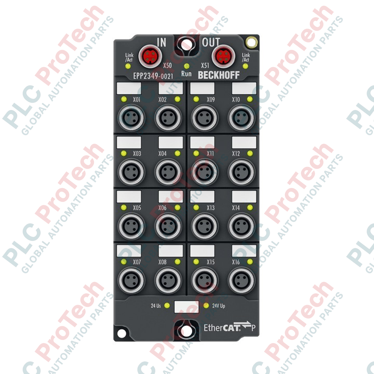
Configured for demanding decentralized environments, the Beckhoff EPP2349-0021 EtherCAT P Box serves as a highly versatile, field-mountable solution integrating 16 digital channels that can be individually parameterized as inputs or outputs. This module utilizes EtherCAT P technology, combining high-speed EtherCAT communication and system/sensor/load power supplies into a single, specialized four-core M8 cable. Housed in a robust, water-tight enclosure, the device enables direct machine-mount installation without an electrical control cabinet, optimizing cable routing and minimizing signal degradation over long physical runs.
Key Features
-
Configurable I/O Architecture: 16 digital channels, each independently operating as a Type 1/3 digital input or a 0.5 A digital output.
-
Unified EtherCAT P Interface: Two P-coded M8 shielded sockets integrate control communications and dual 24 V DC power feeds (Us system/sensor and Up load/actuator) into a unified line.
-
Robust Environmental Protection: IP65, IP66, and IP67 ingress protection rating allows mounting directly in wet, dusty, or high-vibration machinery zones.
-
Short-Circuit Protection: Each output channel is individually short-circuit proof with a collective limit of 3 A across all channels.
-
High-Speed Processing: Extremely low input filter response of 10 microseconds combined with rapid output switching times.
Applications
-
Automotive Assembly Lines: Direct mounting on robotic end-effectors and robotic arms where cabling volume must be minimized.
-
Packaging and Bottling Machinery: Multi-sensor/actuator clusters distributed over large machine areas requiring washdown IP67 ratings.
-
Conveyor and Material Handling Systems: Distributed sensor routing and pneumatic valve control along long mechanical spans.
Technical Specifications
| Parameter |
Specification Value |
| Manufacturer |
Beckhoff Automation |
| Model / Order Number |
EPP2349-0021 |
| Protocol |
EtherCAT |
| Bus Interface |
2 x M8 socket, shielded, screw-type, P-coded (EtherCAT P) |
| Digital Channels |
16, configurable as inputs or outputs |
| I/O Connection Type |
M8 x 1, 3-pin, A-coded |
| Input Filter Time |
10 microseconds |
| Signal Voltage (0 / 1) |
-3 to +5 V DC / 11 to 30 V DC (6 mA typical, EN 61131-2 Type 3) |
| Sensor Supply |
Derived from load voltage Us, max. 0.5 A total, short-circuit proof |
| Rated Load Voltage (Up) |
24 V DC (-15 percent / +20 percent) |
| Max. Output Current |
0.5 A per channel, individually short-circuit proof, max. 3.0 A aggregate |
| Switching Delays |
Typical TON: 60 microseconds; typical TOFF: 300 microseconds |
| Current Consumption from Us |
Typical 100 mA |
| Electrical Isolation |
500 V |
| Operating Temperature Range |
-25 to +60 degC |
| Storage Temperature Range |
-40 to +85 degC |
| Ingress Protection |
IP65, IP66, IP67 (conforms to EN 60529) |
| Standard Approvals |
CE, UL |
| Weight |
approx. 250 g |
| Shipping Weight (Calculated) |
2.0 kg |
Connections and Interfaces
| Connector / Terminal Type |
Pin / Function Assignment |
| EtherCAT P In (M8 P-coded) |
Transmission/Reception data pair + Us (System/Sensor power 24 V DC) and Up (Load/Actuator power 24 V DC) |
| EtherCAT P Out (M8 P-coded) |
Daisy-chain communication and power extension to downstream EtherCAT P modules |
| I/O Channels (M8, 3-pin, A-coded) |
Pin 1: +24 V DC sensor/load supply; Pin 3: GND; Pin 4: Configured digital input or output signal line |
Empirical Engineering Insights
Alternative Models & Compatibility
The EPP2349-0021 uses EtherCAT P (P-coded physical interface). Note that this is not pin-compatible with standard EtherCAT Box units (EP series, such as EP2349) which use separate power injection lines and standard D-coded M8/M12 cables. System design revisions transitioning from EP to EPP must account for the P-coded infrastructure. TwinCAT 3 requires specific XML Device Description (ESI) files matching the exact firmware version of the EPP2349-0021 to support all dynamic channel configuration properties correctly.
Application Pitfalls & Engineering Notes
When daisy-chaining multiple EPP modules, calculate cumulative current drops along both Us (logic/sensors) and Up (actuators) lines. The physical M8 connectors have a maximum continuous current rating of 3 A. If the sum of sensor and actuator draw exceeds this limit, premature undervoltage faults will occur under heavy inductive loads. For high-speed applications, note that the 10-microsecond input filter limits physical pulses to those with frequencies lower than 50 kHz.
Commissioning & Wiring Tips
Always use original Beckhoff pre-assembled P-coded M8 cables to ensure proper shield termination and IP rating continuity. When setting up in TwinCAT System Manager, configure each of the 16 channels explicitly as an input or output in the process data tab before running scan operations. Verify that the combined sensor current does not trigger the 0.5 A cumulative internal current protection shutdown.
Installation Guidelines
CRITICAL SAFETY WARNING
Isolate all electrical power sources (both Us and Up supply lines) before mounting, cabling, or configuring the EtherCAT P module. Working on live systems can result in permanent hardware damage, high voltage discharge through inductive components, and unintended machine movement.
1
Mount the module flat to a clean, structural machine face or bracket using two M3 screws. Avoid applying physical torsion or bending loads to the enclosure.
2
Connect the incoming EtherCAT P cable to the P-coded M8 input port. Hand-tighten the metal locking nut until the seal is completely seated to secure the IP67 protection rating. Do not use excessive force or tools that might damage the threads.
3
Run the out-going EtherCAT P line to downstream modules or insert a certified terminator plug if it is the final node in the local branch.
4
Attach sensor and actuator cables to the A-coded M8 I/O ports. Seal any unused ports with protective plastic M8 caps to keep dust and moisture out of the internal contacts.