Description
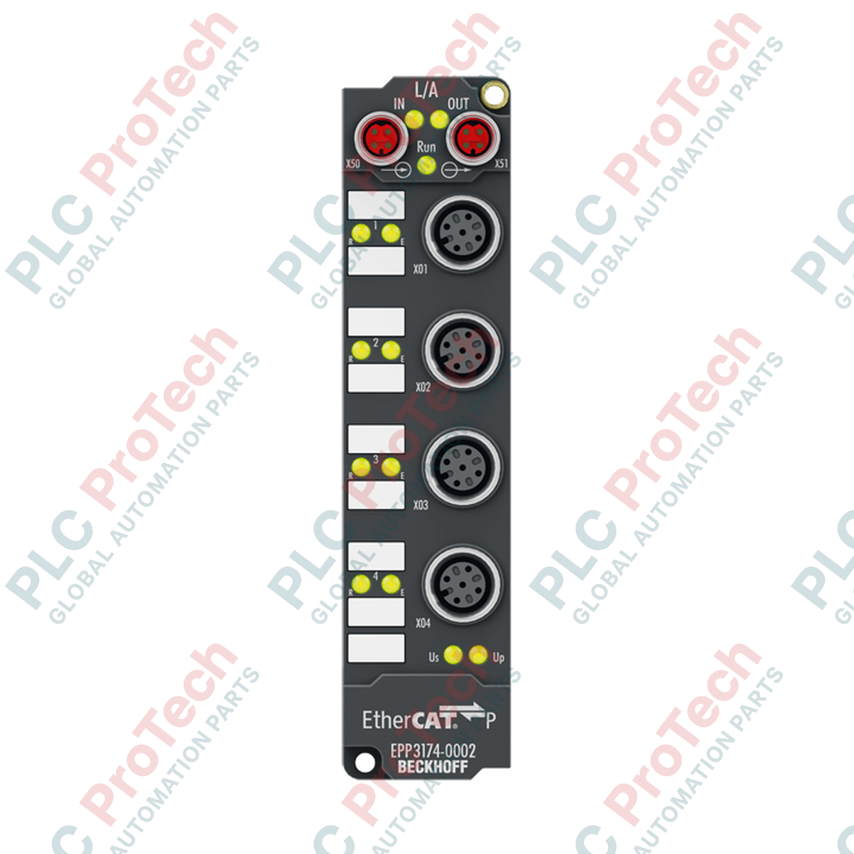
Processing critical field measurements in harsh environments is achieved with the Beckhoff EPP3174-0002, which integrates four parameterizable differential analog inputs into a single, compact IP67 housing. Operating directly over EtherCAT P, this module combines high-speed communication and peripheral power lines (US and UP) into a single, specialized M8 connection, eliminating redundant cabling layouts and reducing overall installation footprints.
Key Features
-
Multi-Signal Compatibility: Supports both voltage (-10 V to +10 V) and current (0 to 20 mA, 4 to 20 mA) interfaces, configurable per channel via CoE.
-
Single-Cable EtherCAT P Technology: Combines EtherCAT communication and power supply (US/UP) in one M8 connector system.
-
High Resolution: Operates at 16-bit analog-to-digital resolution (including sign) for high-accuracy operations.
-
Robust IP-Rated Construction: Fully encapsulated zinc die-cast housing rated for IP65, IP66, and IP67 industrial environments.
-
Advanced Diagnostics: Features built-in status LEDs indicating operational states, network communication, and error conditions.
Industrial Applications
-
De-centralized Field Control: Interfacing analog sensors directly on machinery without control cabinets.
-
Process Automation: Precision flow, pressure, and temperature monitoring in harsh chemical or water treatment facilities.
-
Assembly and Handling Systems: Multi-axis positioning systems requiring distributed analog feedback loops.
Technical Specifications
| Manufacturer |
Beckhoff Automation GmbH & Co. KG |
| Model / SKU |
EPP3174-0002 |
| Inputs |
4 differential analog inputs |
| Signal Type |
-10 V to +10 V, 0 to 20 mA, 4 to 20 mA (individually parameterizable) |
| Resolution |
16 bits (including sign) |
| Conversion Time |
approx. 100 microseconds |
| Measurement Uncertainty |
< +-0.3% (relative to full scale value) |
| Internal Resistance |
> 200 kOhm (voltage) | typ. 85 Ohm + diode voltage (current) |
| Common-Mode Voltage (UCM) |
max. 35 V |
| Input Filter Limit |
5 kHz (configurable) |
| EtherCAT Connection |
2 x M8 socket, shielded, screw-type, P-coded |
| Input Interface |
M12 x 1, 5-pin, A-coded |
| Sensor Power Supply |
Derived from UP (load supply voltage) |
| Current Consumption (US) |
typ. 100 mA |
| Isolation Voltage |
500 V (electrical isolation) |
| Operating Temperature |
-25 to +60 degC |
| Storage Temperature |
-40 to +85 degC |
| Protection Class |
IP65 / IP66 / IP67 (conforms to EN 60529) |
| Approvals |
CE, UL |
| Country of Origin |
Germany |
| Shipping Weight (Calculated) |
0.35 kg |
Connections & Pin Assignments
| M12 Connection (Input Channels) |
Pin Number |
Signal Assignment |
| Analog Inputs (Channels 1 to 4) |
Pin 1 |
+24 V DC Sensor Supply (UP) |
| Pin 2 |
Input + (Differential Positive) |
| Pin 3 |
GND Sensor Supply |
| Pin 4 |
Input - (Differential Negative) |
| Pin 5 |
Shielding / Functional Earth |
Alternative Models & Compatibility
The EPP3174-0002 operates strictly under the EtherCAT P physical layer. It is not a direct physical drop-in replacement for the standard EP3174-0002 (standard EtherCAT), despite sharing identical internal register maps. When integrating into standard EtherCAT networks, a physical media transition module (e.g., Beckhoff EK1310 or EP9224) is required. Ensure the exact XML (ESI) description file matching EPP3174-0002 is loaded into TwinCAT System Manager to prevent communication handshake failure.
Application Pitfalls & Engineering Notes
Because the device derives its power directly from the EtherCAT P M8 trunk line, system designers must complete a strict current-carrying capacity calculation. The maximum total current for the US (system and sensor power) and UP (peripheral load voltage) feeds must not exceed 3.0 A per daisy-chain path. When cascading multiple EPP units, long physical cable lengths can introduce significant DC voltage drops, which can degrade the accuracy of the 24 V DC sensor supply outputs at the M12 interfaces.
Commissioning & Wiring Tips
To transition each input channel between voltage (-10/+10V) and current (4...20mA) operation modes, utilize the CoE (CAN over EtherCAT) configuration matrix in TwinCAT. Modify index 0x8000 (Channel 1) through 0x8030 (Channel 4) to specify the desired measurement range. For highly sensitive current loops, run high-shielded industrial twisted-pair cabling and ensure the M12 metal coupling nut is firmly secured to guarantee complete shield continuity through the chassis ground.
Installation Guidelines
CRITICAL WARNING
Disconnect all active power supplies from the EtherCAT P line (both US and UP lines) before attempting to plug or unplug the M8 and M12 field connectors. Inserting or removing connections under load can cause electrical arcing, resulting in permanent damage to the delicate internal transceiver logic and the destruction of the physical P-coded contacts.
1
Mechanical Mounting: Securely mount the zinc die-cast box to the machinery or mounting plate using two M4 bolts. Verify a low-resistance contact between the mounting tabs and the machine frame to ensure proper functional grounding.
2
Bus Cabling: Align and connect the incoming P-coded EtherCAT P M8 cable to the IN port. Link downstream nodes from the OUT port using standardized, shielded M8 cables. Screw down completely to ensure the IP67 seal.
3
Sensor Integration: Wire the analog field transmitters into the M12 5-pin inputs. Standardize on shielding connections through Pin 5. Seal any unused ports with authentic M12 sealing caps to maintain the ingress rating.
4
Network Configuration: Power up the controller. Perform an online scan in the TwinCAT System Manager, find the node under the EtherCAT Master tree, and verify state transition to 'OP' (Operational) mode.