Description
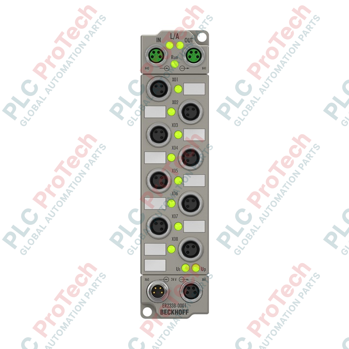
Designed to operate directly in harsh industrial environments without a control cabinet, the Beckhoff ER2338-0001 enables decentralized routing of bidirectional digital control signals. This EtherCAT Box module features 8 digital channels that are individually and freely configurable as either inputs or outputs. By supporting dynamic configuration, this module simplifies field I/O layout adjustments and reduces the overall hardware footprint in complex processing lines. Each channel is processed with high temporal precision, offering integrated input filtering and short-circuit protection for connected sensors.
Key Features
-
Flexible I/O Configuration: 8 digital channels that can be configured independently as inputs or outputs.
-
Robust Industrial Housing: Fully cast zinc die-cast construction with IP65, IP66, and IP67 ingress ratings.
-
High-Speed Communication: Dual M8 shielded, screw-type EtherCAT interfaces for direct line topology.
-
Sensor and Load Protection: Short-circuit-proof sensor supply up to 0.5 A total and thermal overload output protection.
-
Standard M8 Connections: A-coded 3-pin M8 sockets provide standard industrial physical interfaces.
Industrial Applications
-
Automotive Assembly Lines: Decentralized sensor and actuator routing on robotic arms and welding cells.
-
Food and Beverage Processing: Washdown zones requiring robust environmental protection without enclosure housing.
-
Conveyor and Material Handling: Localized distribution of photoelectric sensors, solenoid valves, and pneumatic switches.
Technical Specifications
| Technical Parameter |
Specification Value |
| Manufacturer |
Beckhoff |
| Model Number |
ER2338-0001 |
| Protocol |
EtherCAT |
| Bus Interface |
2 x M8 socket, shielded, screw type |
| Number of Channels |
8 digital inputs or outputs, freely configurable |
| I/O Connections |
M8 x 1, 3-pin, A-coded |
| Input Filter Time |
10 microseconds |
| "0" Signal Voltage Range |
-3 to +5 V |
| "1" Signal Voltage Range |
11 to 30 V, 6 mA input current (EN 61131-2, type 3) |
| Sensor Supply |
From load supply voltage, max. 0.5 A total, short-circuit proof |
| Supported Load Types |
Ohmic, inductive, lamp load |
| Rated Load Voltage |
24 V DC (-15% / +20%) |
| Max. Output Current |
0.5 A per channel |
| Switching Times |
typ. TON: 50 microseconds, typ. TOFF: 100 microseconds |
| Current Consumption (US) |
120 mA |
| Auxiliary Power Current |
typ. 20 mA + load |
| Power Supply Interface |
Feed: 1 x M8 male 4-pin; Downstream: 1 x M8 female 4-pin |
| Electrical Isolation |
500 V |
| Protection Rating |
IP65/IP66/IP67 (conforms to EN 60529) |
| Operating Temperature |
-25 to +60 degC |
| Storage Temperature |
-40 to +85 degC |
| Physical Module Weight |
approx. 265 g |
| Shipping Weight (Calculated) |
2.0 kg |
Port and Wiring Configurations
| Interface Type |
Connector Form Factor |
Assignment & Purpose |
| EtherCAT Bus Input/Output |
2 x M8 socket, shielded, screw-type |
EtherCAT communication downstream/upstream linking. |
| Digital I/O Channels (0-7) |
8 x M8 female socket, 3-pin, A-coded |
Configurable digital signal and sensor supply. Pin 1: +24 V DC sensor supply, Pin 3: GND, Pin 4: Input/Output signal. |
| Power Supply Feed |
1 x M8 male socket, 4-pin |
System/sensor voltage (Us) and peripheral load voltage (Up). |
| Power Supply Downstream |
1 x M8 female socket, 4-pin |
Feed-through power to adjacent EtherCAT Box modules. |
Empirical Engineering Insights
Alternative Models & Compatibility
The ER2338-0001 features fully configurable channels, which makes it an ideal, high-efficiency spare part replacing either pure digital input (ER1008) or pure digital output (ER2008) units in machine modifications. Note that TwinCAT ESI (EtherCAT Slave Information) configurations must specifically define the operational profile (Input vs. Output mode) for each channel to match the physical wiring.
Application Pitfalls & Engineering Notes
Thermal management inside completely enclosed, non-ventilated routing channels must be monitored closely. Although rated up to +60 degC ambient, driving all 8 outputs at their maximum 0.5 A inductive rating simultaneously causes significant localized heating within the cast housing. Ensure proper spacing or metallic surface heat sinking is utilized if cumulative output current exceeds 3.0 A.
Commissioning & Wiring Tips
During commissioning, verify that the Us (system power) and Up (load power) loops are isolated appropriately if safety relays are installed. A common fault is tying Us and Up to the same field supply line, which overrides safety-related external output de-energization loops. Always torque all M8 connectors to exactly 0.4 Nm to preserve environmental sealing.
Installation Guidelines
CRITICAL WARNING: Prior to wiring, mounting, or performing maintenance on the module, ensure all 24 V DC control power (Us) and peripheral load power (Up) sources are completely de-energized. Verify the absence of voltage using a calibrated test instrument. Failure to isolate power lines can result in hardware damage or unexpected device actuation, leading to equipment damage or personal injury.
1
Mechanical Mounting: Secure the physical chassis directly to the machine frame or mounting profile using two M3 screws. Ensure the mounting surface is clean to optimize thermal conduction.
2
EtherCAT and Power Cabling: Connect the shielded M8 EtherCAT cabling to the IN and OUT ports. Connect the 4-pin M8 power cable supplying 24 V DC to the input feed port. Secure unused ports with IP67 protective caps to prevent ingress of moisture or particulates.
3
Software Configuration: Power up the system, scan the EtherCAT network in TwinCAT, and import the relevant XML (ESI) file. Map the individual channels as inputs or outputs within your PLC project prior to system logic execution.