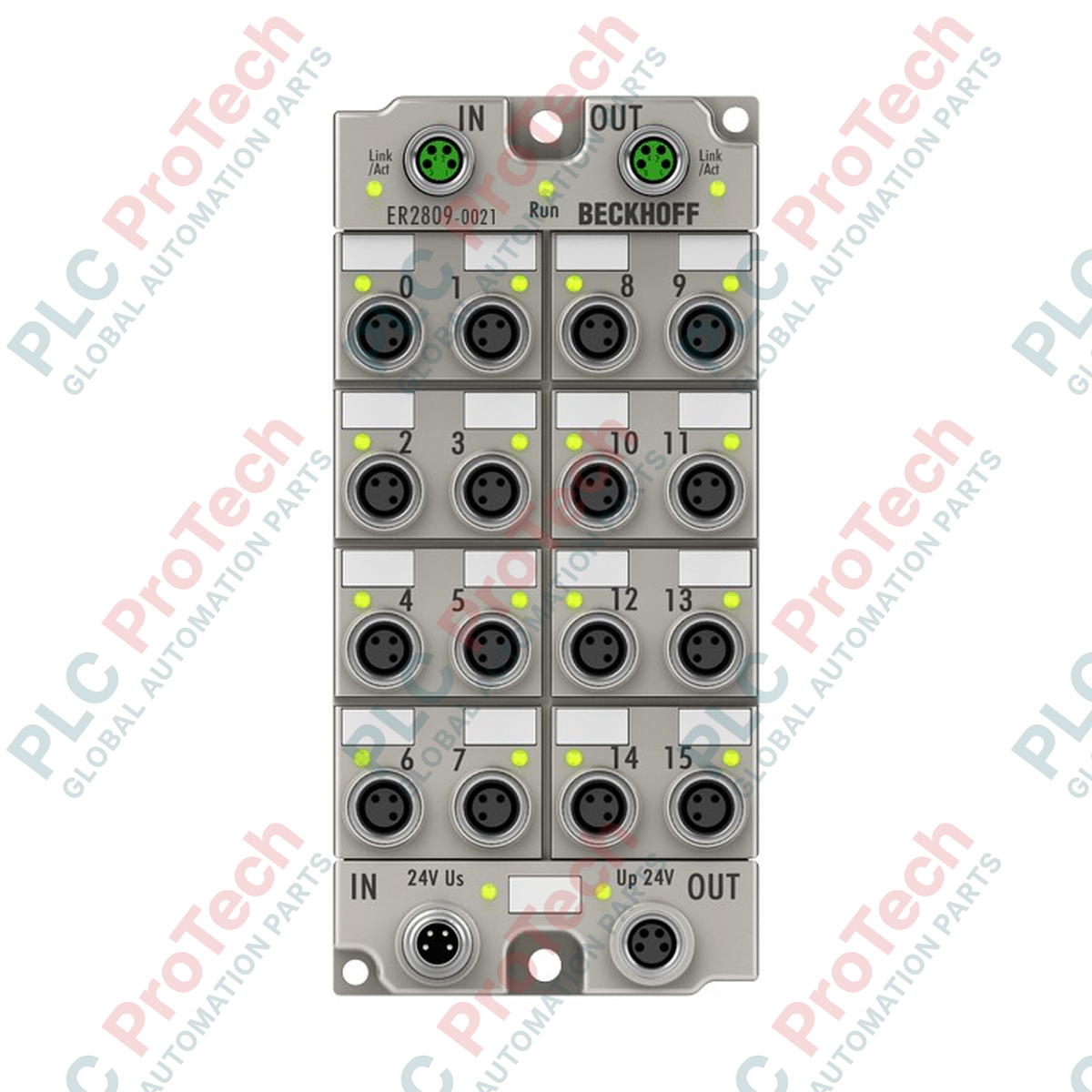
Description
Decentralized automation architectures requiring high channel density at the machine level benefit directly from the Beckhoff ER2809-0021 EtherCAT Box. This field-mountable I/O device processes up to 16 digital output signals, distributing 24 V DC control commands directly to ohmic, inductive, and lamp loads. Housed in a robust, zinc die-cast casing, the module bypasses the need for protective electrical cabinets, establishing reliable IP67 protection directly on the machine frame. Integrated short-circuit protection and electrical isolation ensure robust system safety during transient events.
Product Features
-
16 Digital Output Channels: Highly consolidated signal density for complex field-level actuator arrays.
-
Individually Short-Circuit Proof: Each output provides individual current limiting to shield downstream components from electrical faults.
-
Industrial M8 Interfaces: Features 3-pin, A-coded output connection points and dual-channel M8 EtherCAT interface sockets.
-
Heavy-Duty Die-Cast Housing: Designed with a zinc alloy casing to withstand severe mechanical impact and abrasive industrial conditions.
-
IP65/66/67 Submersible Rating: Complete ingress protection against moisture, cooling lubricants, and particulate contamination.
Applications
- Modular machine building and automated assembly lines with decentralized field layouts.
- Robotic end-of-arm tooling and mechanical material handling setups.
- High-vibration manufacturing environments, conveyor systems, and packaging machinery.
Technical Specifications
| Parameter |
Value / Specification |
| Manufacturer |
Beckhoff |
| Model Number |
ER2809-0021 |
| Protocol |
EtherCAT |
| Bus Interface Connection |
2 x M8 socket, shielded, screw type |
| Number of Digital Outputs |
16 |
| Output Connections |
M8 x 1, 3-pin, A-coded |
| Permitted Load Types |
Ohmic, inductive, lamp load |
| Nominal Output Voltage |
24 V DC (-15% / +20%) |
| Max. Output Current |
0.5 A per channel (individual short-circuit proof), max. 4 A total sum |
| Switching Times (Typical) |
TON: 60 us, TOFF: 300 us |
| Short-Circuit Current Limit |
Max. 1.5 A |
| Current Consumption (US Logic) |
Typical 130 mA |
| Auxiliary Power Current (UP) |
Typical 20 mA + load current |
| Power Supply Connections |
Feed: 1 x M8 male socket, 4-pin; Downstream: 1 x M8 female socket, 4-pin |
| Electrical Isolation |
500 V (control voltage / auxiliary voltage to fieldbus) |
| Operating Temperature |
-25 to +60 degC |
| Storage Temperature |
-40 to +85 degC |
| Vibration/Shock Resistance |
Conforms to EN 60068-2-6 / EN 60068-2-27 |
| EMC Immunity/Emission |
Conforms to EN 61000-6-2 / EN 61000-6-4 |
| Protection Rating |
IP65/66/67 (conforms to EN 60529) |
| Approvals & Markings |
CE, UL |
| Unit Weight |
Approx. 450 g |
| Shipping Weight |
2.0 kg |
Connections & Interfaces
| Interface Type |
Connector Configuration |
Functional Description |
| EtherCAT Input / Output |
M8 socket, 4-pin, shielded |
Dual shielded port topology for direct daisy-chain fieldbus coupling. |
| Power Supply Feed |
M8 male connector, 4-pin |
Accepts 24 V DC system power (US) and 24 V DC auxiliary load power (UP). |
| Power Downstream |
M8 female socket, 4-pin |
Power forwarding connection to downstream EtherCAT Box modules. |
| Digital Outputs |
M8 x 1, 3-pin, A-coded |
Individual actuator signal delivery and return loop. |
Empirical Engineering Insights
Alternative Models & Compatibility
The ER2809-0021 utilizes a die-cast zinc housing designed to substitute plastic-housed EP2809 equivalents directly. When upgrading plastic EP components to the zinc ER line, verify mechanical clearances, as the die-cast housing has minor physical envelope variations and increased physical weight. Software configurations in TwinCAT remain fully backward-compatible; swapping modules does not require rebuilding standard EtherCAT network topologies or logic tasks.
Application Pitfalls & Engineering Notes
A common operational failure stems from thermal compounding. While each channel supports up to 0.5 A, the maximum cumulative load across all channels cannot exceed 4 A. Operating all 16 channels at full rating simultaneously will trigger thermal shutdown or permanent circuit trace degradation. When deploying inside sealed, unventilated zones or under high ambient solar loads, construct an external thermal pathway or stagger actuator execution to manage steady-state thermal accumulation.
Commissioning & Wiring Tips
To minimize electrical interference and downstream communication dropouts, ensure the EtherCAT network cables use shielded M8 connectors, with the shield coupled continuously to the machine chassis ground. Separate your 24 V DC system supply (US) from the auxiliary power supply (UP) loop; doing so allows emergency-off circuits to de-energize UP load circuits while maintaining communication and diagnostic functions on the US logic loop.
Installation Guidelines
CRITICAL WARNING: Prior to commencing installation, mechanical mounting, or wiring adjustments, ensure all high-voltage and low-voltage field power supplies (US and UP) are physically disconnected. Verify that capacitors and residual circuit elements are fully discharged. Failure to isolate power systems can cause electrical shock, component damage, or unexpected industrial machinery movement.
1
Mount the module directly to a flat, vibration-resistant machine frame surface using standard M3 bolts or DIN rail adaptors.
2
Establish the machine frame ground reference by securing a low-impedance grounding strap to the integrated ground contact on the module body.
3
Connect the shielded M8 EtherCAT communication cables to the IN and OUT ports, checking that the screw collars are torqued correctly to seal against fluid ingress.
4
Attach the M8 power distribution cable to feed logic power (US) and output circuit power (UP), then secure all remaining 16 M8 sensor/actuator channel leads.