Description
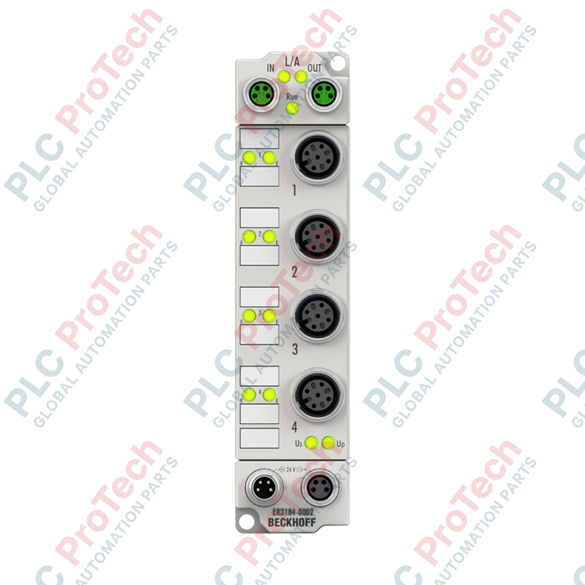
Designed for direct field deployment without a control cabinet, the Beckhoff ER3184-0002 EtherCAT Box provides high-precision processing of up to four analog input signals in harsh environments. This module enables software-parameterizable selection between voltage (-10/0 to +10 V) and current (0/4 to 20 mA) measurements on a per-channel basis. Housed in a robust, zinc die-cast shell with an IP67 protection rating, it processes signals with a 16-bit resolution and fast conversion times, making it ideal for distributed machinery and process loops requiring high noise immunity.
Features
- Four single-ended, individually configurable analog inputs.
- 16-bit analog-to-digital resolution (including sign) for high signal fidelity.
- Robust IP65/66/67 physical encapsulation, eliminating the need for protective field enclosures.
- High-speed conversion rate of approximately 100 microseconds per channel.
- Support for Distributed Clocks (DC) to ensure tight synchronization across the entire EtherCAT network.
- Configurable input filter limit frequency up to 5 kHz.
- Standardized M12 input connections alongside reliable M8 EtherCAT communication ports.
Applications
- Cabinet-free on-machine sensor consolidation in automotive and manufacturing assembly lines.
- Distributed process parameters monitoring, including flow, temperature, and pressure transmitters.
- Automated materials handling and conveyor systems operating in wet or dusty processing plants.
- High-speed parameter recording systems utilizing TwinCAT-based distributed clocks.
Technical Specifications Table
| Parameter |
Specification |
| Manufacturer |
Beckhoff Automation |
| Model Number |
ER3184-0002 |
| Number of Inputs |
4 (single-ended) |
| Signal Ranges |
-10 to +10 V | 0/4 to 20 mA (parameterizable per channel) |
| Resolution |
16 bits (including sign) |
| Conversion Time |
~ 100 microseconds |
| Internal Resistance |
> 200 kOhm (voltage) | typ. 85 Ohm + diode voltage (current) |
| Common-Mode Voltage (UCM) |
Max. 35 V |
| Measurement Uncertainty |
< ±0.3 % (relative to full scale value) |
| Distributed Clocks (DC) |
Supported, high-precision synchronization |
| Input Filter |
Configurable, limit frequency 5 kHz |
| Nominal Power Supply |
24 V DC (-15% / +20%) |
| Current Consumption |
120 mA from US |
| Electrical Isolation |
500 V |
| IP Rating |
IP65 / IP66 / IP67 (conforms to EN 60529) |
| Operating Temperature |
0 to 55 degC |
| Storage Temperature |
-25 to 85 degC |
| Weight |
Approx. 265 g |
| Standards & Approvals |
CE, UL |
Connections and Interfaces
| Connector / Pin |
Functional Assignment |
| M8 Bus Sockets (2 x Shielded) |
EtherCAT IN / EtherCAT OUT |
| M12 Socket Pin 1 |
+24 V DC sensor supply (derived from UP) |
| M12 Socket Pin 2 |
Analog input + (Voltage / Current) |
| M12 Socket Pin 3 |
GND (Sensor supply ground) |
| M12 Socket Pin 4 |
Analog input - (Signal ground) |
| M12 Socket Pin 5 |
Shield / Functional Earth (FE) |
Empirical Engineering Insights
Alternative Models & Compatibility
The ER3184-0002 serves as a ruggedized, field-mounted alternative to the cabinet-based EP3184-0002 EtherCAT Box. Both modules feature identical electronic behavior and parameterization registers via TwinCAT. However, the ER3184 housing is fabricated from heavy-duty zinc die-cast, whereas EP-series modules utilize lighter plastic housings. Direct firmware drop-in compatibility is maintained from TwinCAT 2.11 Build 2040 and TwinCAT 3.x onwards.
Application Pitfalls & Engineering Notes
When configuring channels for current mode (0 to 20 mA or 4 to 20 mA), the internal input pathway pathways route through an 85 Ohm shunt in series with a protection diode. System designers must ensure that the driving sensor has sufficient compliance voltage to overcome this diode forward drop under full-scale current loops, especially when powering passive loop-powered devices.
Commissioning & Wiring Tips
To guarantee IP67 sealing and maintain shielding performance, all unused M12 and M8 connections must be sealed using authentic Beckhoff protective caps. Ground the zinc housing directly to the machine bed through a dedicated low-impedance earthing strap. This prevents ground loops and ensures high-frequency noise is successfully shunted away from the sensitive 16-bit A/D converters.
Installation Guidelines
CRITICAL WARNING: De-energize all primary field power supplies (US and UP) before mounting or connecting the EtherCAT Box. Ground potential differences between physical nodes can cause instantaneous destruction of the logic interface or damage sensor inputs if connections are hot-plugged.
1
Mount the ER3184-0002 to a flat metal surface using two M3 screws through the integral mounting holes to establish a robust mechanical and thermal interface.
2
Attach the M8 EtherCAT communication cables (IN and OUT ports) using a torque wrench calibrated to 0.4 Nm to maintain ingress protection integrity.
3
Connect the analog sensor cables to the appropriate M12 channels. Ensure you apply the proper pinout configuration for active versus passive current loop requirements.
4
Supply 24 V DC to the M8 power inlet (US and UP). Open TwinCAT, scan the EtherCAT loop, and configure the CoE (CAN over EtherCAT) variables to match the sensors' voltage or current profiles.