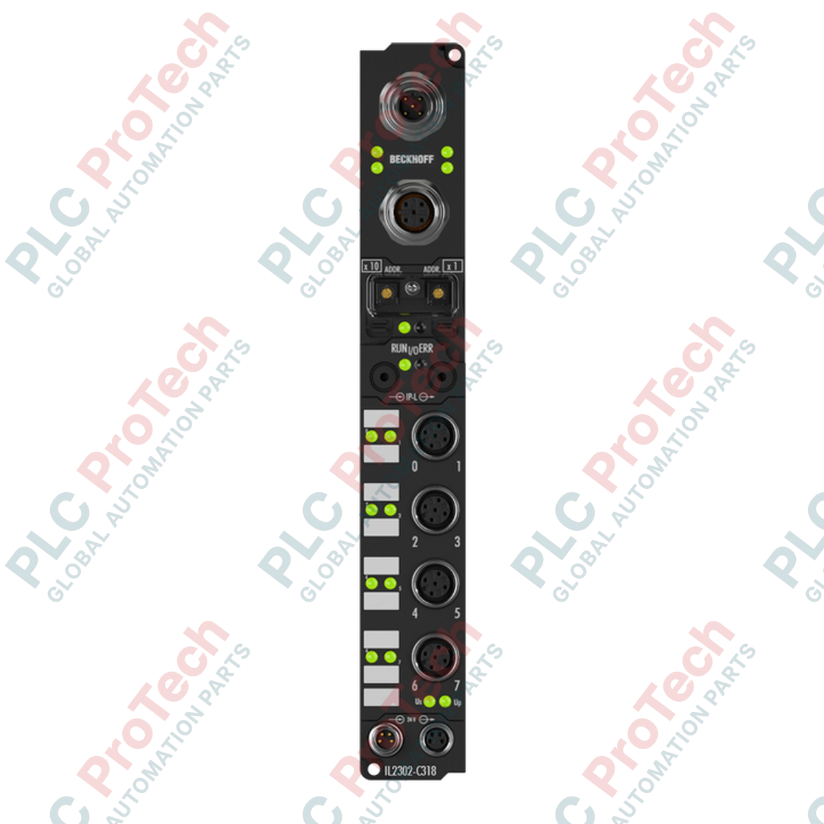
Description
Decentralized machine topologies utilize the Beckhoff IL2302-C318 Fieldbus Box to establish reliable, high-speed connection points without necessitating cabinet space. This high-density module acts as a rugged remote I/O link, featuring built-in PROFIBUS DP communication and support for DP-V1 extensions. By using standard industrial connectors, it streamlines complex field wiring and ensures precise signal acquisition directly on the machinery under demanding operational conditions.
Features
-
Automatic Baud Rate Detection: Automatically senses transmission rates up to 12 Mbaud on the PROFIBUS network.
-
Dual-Path Configuration: Offers versatile parameterization capabilities via the Beckhoff KS2000 software suite or directly through the PLC controller.
-
Robust Connectivity: Equipped with an integrated M12 T-connector (B-coded) for fast, daisy-chained bus routing without external splitters.
-
Dual-Source Power Isolation: Separation of control voltage and load voltage ensures fault propagation protection across downstream lines.
-
Environmentally Sealed: Constructed with a high-durability housing providing IP65, IP66, and IP67 level protection against moisture and particulates.
Applications
-
Automotive Assembly Lines: Distributed sensor and actuator feedback in cabinet-free manufacturing cells.
-
Material Handling & Logistics: Conveyor control and sorting system tracking interfaces.
-
Packaging Machinery: Multi-axis packaging equipment requiring localized I/O nodes.
-
Process Automation: Field installation in high-vibration and washdown-prone environments.
Technical Specifications
| Parameter |
Specification |
| Manufacturer |
Beckhoff Automation |
| Model Number |
IL2302-C318 |
| Data Transfer Rates |
Automatic detection up to 12 Mbaud |
| Bus Interface |
1 x M12 socket (5-pin), 1 x M12 plug (5-pin), B-coded, integrated T-connector |
| Control Supply Voltage |
24 V DC (-15% / +20%) |
| Load Supply Voltage |
According to I/O type |
| Current Consumption (Box Supply) |
85 mA + sensor current consumption (max. 0.5 A) |
| Electrical Isolation |
Control voltage/fieldbus: No; Control voltage/inputs-outputs: According to I/O type |
| Operating Temperature |
0 degC to +55 degC |
| Storage Temperature |
-25 degC to +85 degC |
| Vibration/Shock Resistance |
Conforms to EN 60068-2-6 / EN 60068-2-27 |
| EMC Immunity/Emission |
Conforms to EN 61000-6-2 / EN 61000-6-4 |
| Protection Class |
IP65 / IP66 / IP67 (conforms to EN 60529) |
| Approvals |
CE, UL |
| Shipping Weight (Calculated) |
2.0 kg |
Connections and Interfaces
| Connection Port |
Connector Type |
Pin Allocation / Function |
| PROFIBUS Input |
M12 Plug (Male), 5-pin, B-coded |
Standard PROFIBUS signal connections |
| PROFIBUS Output |
M12 Socket (Female), 5-pin, B-coded |
Tee-connector output for daisy chain expansion |
| Power Feed |
M8 Plug (Male), 4-pin |
Control voltage feed (24 V DC) |
| Power Downstream |
M8 Socket (Female), 4-pin |
Power distribution feed to adjacent modules |
Empirical Engineering Insights
Alternative Models & Compatibility
This unit is fully compatible with standard Beckhoff IP-Link extension boxes. When integrating this module into existing PROFIBUS master systems, ensure that the active GSD hardware definition file matches the revision code of the installed firmware to prevent diagnostic mismatches during cyclical bus startup.
Application Pitfalls & Engineering Notes
Because this module does not provide electrical isolation between the 24 V DC control voltage and the fieldbus communication lines, any differential in ground reference potentials can lead to communication degradation. It is highly recommended to run a common low-impedance ground bonding conductor across all nodes in distributed cabinet-free topologies.
Commissioning & Wiring Tips
Always use standard B-coded PROFIBUS cabling to prevent mismatching with sensory connections. When connecting the M8 power distribution downstream ports, ensure the cumulative sensor load does not exceed 4 A across the power-feed run. Tighten all M8/M12 connectors with a calibrated torque wrench to the manufacturer-specified values (typically 0.4 Nm for M8, 0.6 Nm for M12) to ensure the integrity of the IP67 moisture seal.
Installation Guidelines
CRITICAL WARNING: De-energize all primary, auxiliary, and load power sources prior to connecting or disconnecting the PROFIBUS bus cables or power feeds. Failing to remove power before handling connections in wet environments can result in physical shock hazards, short-circuit paths, and permanent destruction of internal I/O diagnostic logic.
1
Position the module on a flat, vibration-resistant mounting surface utilizing the integrated dual screw mounting holes. Ensure the surface is free from debris.
2
Connect the PROFIBUS DP interface using pre-molded M12 B-coded cables. Ensure any unused bus ports are sealed using IP67-rated protective caps.
3
Attach the M8 24 V DC control voltage input to the male power-feed port. Ensure proper polarity is observed on the feeding terminals.
4
Apply the final tightening torque to all dynamic connectors, power up the main control supply, and verify link activity LED indicators.