Description
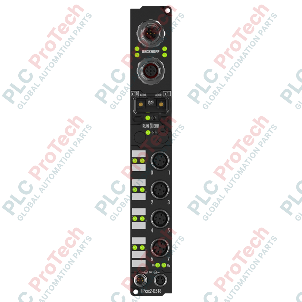
Designed for direct, machine-mount distributed deployment, the Beckhoff IP2002-B518 coordinates high-density localized outputs without the footprint or cost of protective control enclosures. This decentralized fieldbus box integrates 8 digital outputs operating at 24 V DC, utilizing CANopen protocol communications to optimize real-time control architectures. With integrated M12 T-junction connectors, this device enables clean line-topology bus configurations directly on physical machine frames. Wrapped in a ruggedized polyamide housing, it delivers reliable IP67 protection against moisture, dust, and continuous industrial vibrations.
Features
-
8 Digital Outputs: Delivers up to 0.5 A per channel, fully compatible with resistive, inductive, and lamp load setups.
-
Integrated T-Connector: Built-in M12 5-pin male and female connectors enable straightforward physical looping of the CANopen bus.
-
Short-Circuit Diagnostics: Individual output channels feature electronic short-circuit protection to insulate localized faults.
-
Flexible Power Distribution: Dedicated M8 connections isolate control logic power (Us) from physical load power (Up).
-
Aggressive Environmental Rating: Rated for IP65/66/67 operation, securing signal paths in high-spray washdown zones.
Applications
-
Pneumatic Valve Block Control: Direct switching of manifold pilot valves on moving gantry assemblies.
-
Material Handling Conveyors: Localized routing of sorting diverters, stop gates, and indicator lights.
-
Automotive Assembly Tooling: Robotic end-effector output distribution where control enclosure space is non-existent.
-
Packaging and Bottling Machinery: Multi-station actuator triggering in high-moisture production zones.
Technical Specifications Table
| Parameter |
Value / Specification |
| Manufacturer |
Beckhoff |
| Model Number |
IP2002-B518 |
| Module Type |
8-Channel Digital Output Fieldbus Box |
| Protocol / Interface |
CANopen (16 Tx / 16 Rx PDOs supported) |
| Supported Baud Rates |
10 kbaud to 1 Mbaud (automatic detection) |
| Number of Outputs |
8 (single-wire connection) |
| Nominal Output Voltage |
24 V DC (-15 % / +20 %) |
| Max. Output Current |
0.5 A per channel (individually short-circuit proof) |
| Electrical Isolation |
500 V (Control voltage to fieldbus) |
| Control Voltage Supply (Us) |
24 V DC, typical 45 mA current consumption |
| Fieldbus Connection |
1 x M12 plug (5-pin), 1 x M12 socket (5-pin) (Integrated T-Connector) |
| Power Supply Feed |
1 x M8 male (4-pin); Downstream loop: 1 x M8 female (4-pin) |
| Housing Material |
Polyamide PA6 (XXL housing) |
| Operating Temperature |
0 to +55 degC |
| Storage Temperature |
-25 to +85 degC |
| Protection Class |
IP65 / IP66 / IP67 (conforms to EN 60529) |
| Dimensions (W x H x D) |
30 mm x 210 mm x 26.5 mm |
| Shipping Weight (Calculated) |
2.0 kg |
Connections and Interfaces
| Connector / Interface |
Pin Number |
Signal Assignment |
| CANopen Fieldbus (M12) |
Pin 1 |
CAN_SHLD (Shield) |
| Pin 2 |
V+ (Optional External Power) |
| Pin 3 |
CAN_GND (Ground) |
| Pin 4 |
CAN_H (Signal High) |
| Pin 5 |
CAN_L (Signal Low) |
| Power Supply Feed (M8) |
Pin 1 |
Us +24 V DC (Control Voltage for Electronics) |
| Pin 2 |
Up +24 V DC (Load Voltage for Digital Outputs) |
| Pin 3 |
GNDs (Control Ground) |
| Pin 4 |
GNDp (Load Ground) |
Empirical Engineering Insights
Alternative Models & Compatibility
The B518 variant serves as an drop-in optimization over legacy B510 fieldbus boxes. Because the IP2002-B518 integrates the T-connector directly within its molded housing, it completely replaces the requirement for external "Z1001" network splitter adapters, decreasing field cabling clutter and potential points of ingress failure.
Application Pitfalls & Engineering Notes
While each individual channel features short-circuit current protection peaking at approximately 1.5 A under fault conditions, the cumulative load across all 8 output channels must not exceed the maximum current rating of the feeding M8 terminal (typically capped at 4 A total across Up). Ensure appropriate current-budget configurations are calculated for simultaneously active inductive loads.
Commissioning & Wiring Tips
To access the decimal rotary node-ID configuration switches, remove the protective cover plate using a small flat screwdriver. Ensure this plate is re-seated with its sealing gasket completely flush to preserve the IP67 integrity. Additionally, note that this module does not integrate internal CAN termination resistors; a physical M12 termination plug must be added at the terminal physical drop-point of the network.
Installation Guidelines
CRITICAL WARNING: Ensure all power distribution lines (Us and Up) are fully de-energized prior to connecting or disconnecting any M8 or M12 cables. Connecting active power lines to IP-series modules can result in contact-arc damage and compromise internal diagnostic logic.
1
Mechanical Mounting: Mount the module directly onto a flat machinery support structure using the two 3.5 mm diameter fixing points using M3 screws. Ensure no torsional stress is applied to the PA6 housing.
2
Configure Node ID: Unscrew the protective cover. Using a rotary switch tool, set the correct CANopen Node ID. Verify the baud rate setting is configured correctly (defaulting to auto-detection). Re-seal the cover.
3
Bus & I/O Connections: Connect the M12 fieldbus lines to the integrated T-connector ports. Tighten the knurled metal collars hand-tight (0.6 Nm torque recommended) to guarantee environmental protection.
4
Power Integration: Hook up the incoming 4-pin M8 feed. If multiple boxes are in line, loop from the downstream M8 female connector to the subsequent device.