Description
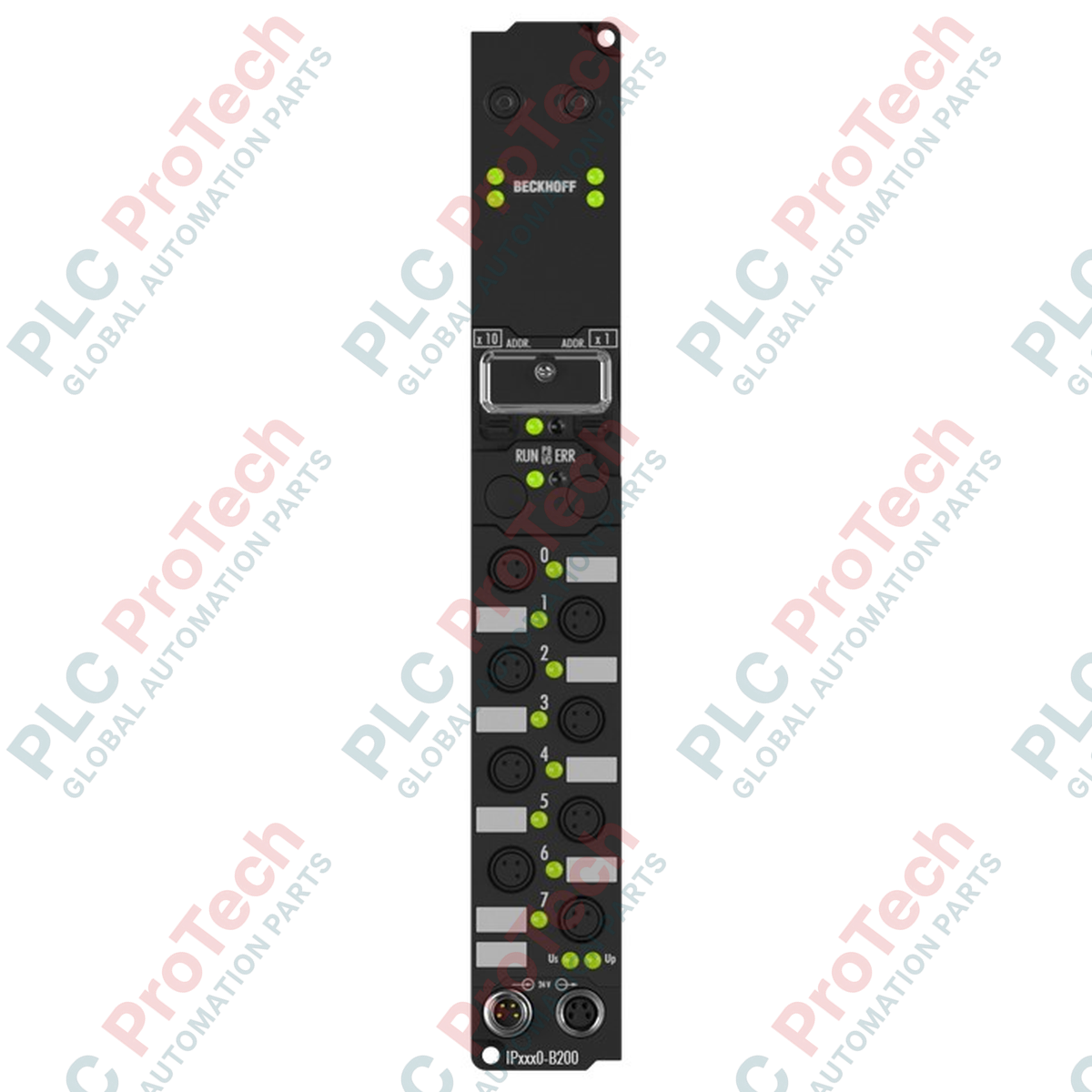
Designed for noise-immune distributed industrial automation, the Beckhoff IP2020-B200 establishes robust control node links through a high-speed optical fiber interface. Operating as a decentralized Fieldbus Box, this module integrates seamlessly into Lightbus ring topologies to offer rapid data transmission speeds of 2.5 Mbaud over optical fiber lines. Its design provides native galvanic isolation and absolute immunity to electromagnetic interference (EMI), making it optimal for heavy-duty manufacturing zones. The module utilizes standardized M8 connection interfaces for control power routing and features specialized fiber-optic sockets configured for direct-plug compatibility.
Features
-
High-Speed Lightbus Interface: Operates at a constant 2.5 Mbaud rate for deterministic control cycles.
-
Immunity to Electrical Noise: Utilizes dual fiber-optic connections for total electrical isolation between control logic and the field network.
-
Configurable Field Parameters: Supports full configuration through Beckhoff KS2000 commissioning software or directly via the master PLC program.
-
Flexible Auxiliary Power Routing: Separate control voltage and load voltage circuits mapped across dedicated 4-pin M8 sockets.
-
Robust Environmental Protection: Sealed IP67-rated housing supports cabinet-free installation directly on machinery.
Applications
-
Automotive Assembly Lines: High-EMI welding environments requiring secure, non-conductive data transfer.
-
Packaging and Material Handling: Distributed topologies with high mechanical vibration and long cable runs.
-
Hazardous/Corrosive Areas: Applications where optical isolation prevents ground loops and spark hazards.
Technical Specifications
| Parameter |
Specification Value |
| Manufacturer |
Beckhoff |
| Model Designation |
IP2020-B200 |
| Bus Interface |
2 x fiber-optic socket for plug ZS1020-0010 |
| Data Transfer Rate |
2.5 Mbaud |
| Control Supply Voltage |
24 V DC (-15% / +20%) |
| Power Feed Connector |
1 x M8 male socket, 4-pin |
| Downstream Power Connector |
1 x M8 female socket, 4-pin |
| Electrical Isolation |
Control voltage to fieldbus: Yes |
| Operating Temperature |
0 degC to 55 degC |
| Storage Temperature |
-25 degC to 85 degC |
| Ingress Protection Rating |
IP65 / IP66 / IP67 (conforms to EN 60529) |
| Vibration Resistance |
Conforms to EN 60068-2-6 |
| Shock Resistance |
Conforms to EN 60068-2-27 |
| Standards & Approvals |
CE, UL |
| Net Weight |
Approx. 250 g |
| Shipping Weight (Calculated) |
0.55 kg (including packaging material) |
Connections and Interfaces
| M8 Terminal Pin |
Circuit Assignment |
Functional Description |
| Pin 1 |
+24 V DC Us |
Control supply voltage for internal electronics |
| Pin 2 |
+24 V DC Up |
Auxiliary/load supply voltage for sensors/actuators |
| Pin 3 |
GND Us |
Reference ground for control electronics |
| Pin 4 |
GND Up |
Reference ground for sensor/actuator power circuits |
Empirical Engineering Insights
Alternative Models & Compatibility
The IP2020-B200 relies on the standard Beckhoff Lightbus protocol (II2001 or FC2001 PCI cards). If migrating to EtherCAT-based infrastructure, consider transitioning to the EP-series Fieldbus Boxes (e.g., EP1111 or EP2028-0002). For maintenance of older optical rings, keep spare ZS1020-0010 plastic optical fiber plugs on hand, as connection alignment is critical to maintaining signal budget across consecutive nodes.
Application Pitfalls & Engineering Notes
Plastic optical fibers (POF) must be cut perfectly perpendicular using a dedicated optical fiber cutter (such as Beckhoff ZS1023-0003). Ragged or angled cuts lead to high optical attenuation, triggering intermitted packet drops and system fault codes on the master controller. Maintain a minimum bend radius of 25 mm for the optical fiber to avoid permanent stress damage to the physical core.
Commissioning & Wiring Tips
When configuring node addresses via KS2000, ensure your PC-to-node interface baud rate is set to match the hardware default. When checking the optical power level budget, use the diagnostic register status flags inside the PLC control word to verify the optical link quality before putting the system into high-demand operation.
Installation Guidelines
CRITICAL WARNING: De-energize all primary and auxiliary power systems (Us and Up) before inserting or removing the M8 connectors or optical fiber connections. Failure to do so can cause voltage spikes on signal pins or physical contamination of open optical sockets, resulting in permanent optical link degradation.
1
Mount the IP2020-B200 securely to a flat, rigid panel surface or machine frame using M4 industrial mounting bolts. Do not apply mechanical tension to the housing.
2
Insert the fiber-optic plugs (ZS1020-0010) into the dedicated optical ports. Ensure they seat firmly and the retention sleeve clicks or secures tightly.
3
Connect the 4-pin M8 auxiliary power cables to the male input port. Torque the M8 threaded connector ring to 0.4 Nm to guarantee the IP67 moisture seal.
4
If running downstream modules, extend power out of the female M8 port using industrial shielded cabling. Seal any unused ports with protective IP67 plastic caps.