Description
Operating as a dedicated master interface between the internal K-bus backplane and actuator-sensor field networks, the Beckhoff KL6201 enables direct and seamless integration of AS-Interface (AS-i) networks into modular I/O configurations. This single-channel master module processes signals from both digital and analog AS-i slaves, converting field-level communication into K-bus protocols for processing by central controllers. The unit features selectable process image widths to balance data throughput and diagnostic feedback, offering an optimal network expansion interface for medium-to-large industrial control environments.
Features
-
Multi-Specification Compatibility: Supports AS-Interface specifications V2.0 and V2.1, ensuring compatibility with older and current slave generations.
-
Scalable Slave Capacities: Connects up to 31 slaves under V2.0 protocols or up to 62 slaves under V2.1 protocols.
-
Configurable Process Image: Selectable transmission widths of 12, 22, or 38 bytes, with 6 bytes reserved for parameter configuration.
-
Integrated Status Diagnostics: Continuous hardware-level diagnostics for power failures, slave communication drops, and configuration parameters.
-
Flexible Address Assignment: Auto-addressing capabilities directly through the control software interface or manual assignment via KS2000.
-
High Galvanic Isolation: Provides robust 500 V testing isolation between the internal K-bus and the external AS-i field lines.
Applications
-
Automated Conveyor Systems: Distributed sensor and actuator monitoring along long conveyor paths.
-
Pneumatic Valve Manifold Control: Interfacing multi-point industrial solenoid valves to central PLC networks.
-
Hazardous Area Demarcation: Deployment in explosive atmospheres when matched with specific ATEX-certified installation criteria.
Technical Specifications
| Parameter |
Specification Value |
| Manufacturer |
Beckhoff Automation |
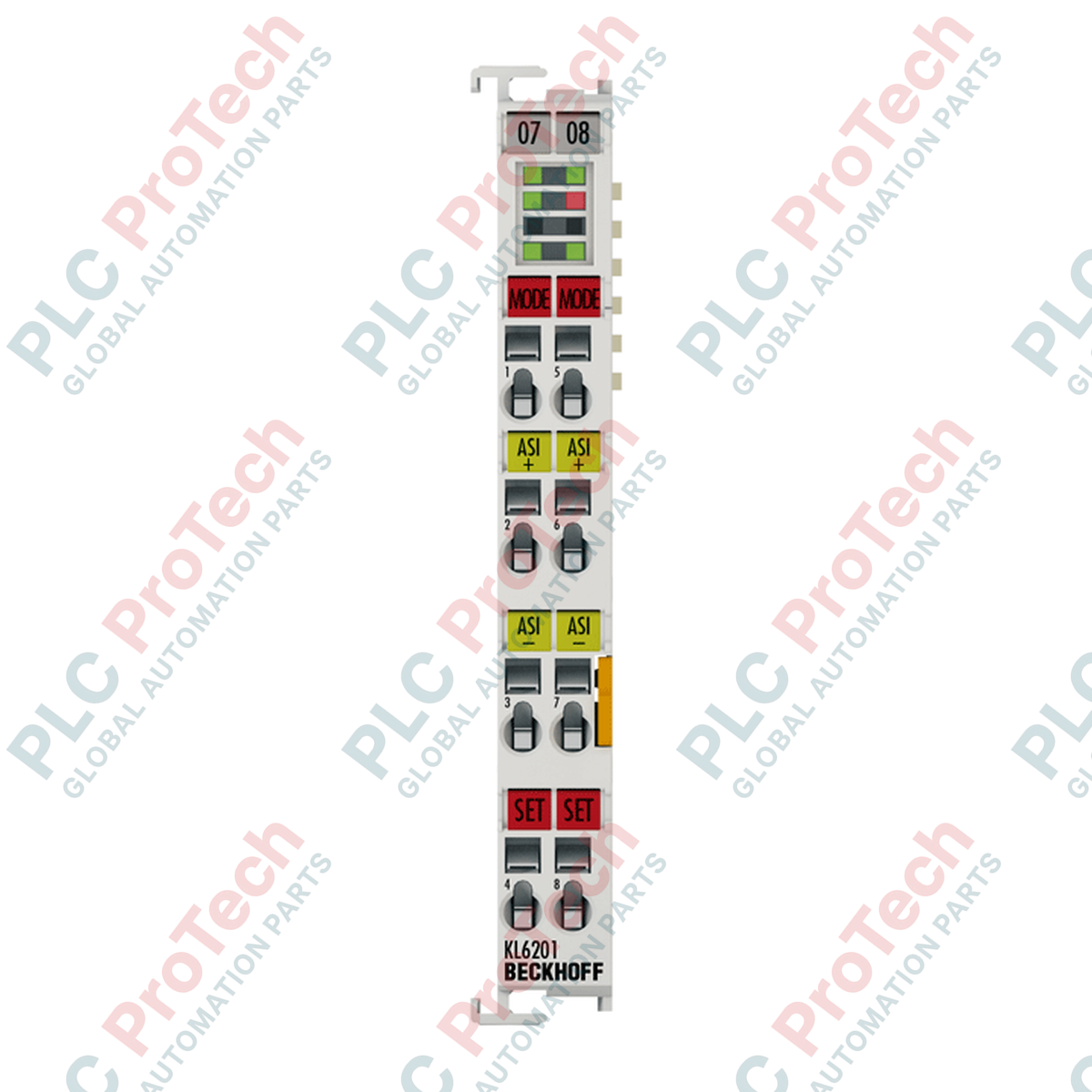
| Model Number |
KL6201 |
| Technology Type |
AS-Interface Master |
| Number of Channels |
1 AS-i channel |
| Specification Version |
AS-Interface V2.0, V2.1 |
| Connected Slaves Capacity |
Up to 31 (V2.0) / up to 62 (V2.1) |
| Compatible Slave Types |
Digital and analog field slaves |
| Backplane Current Draw (K-bus) |
Typ. 55 mA |
| AS-Interface Power Consumption |
Typ. 60 mA |
| Cycle Time |
Max. 5 ms (for 31 connected devices) |
| Electrical Isolation |
500 V (AS-Interface/K-bus backplane) |
| Power Contacts Through-Bus |
None (no passive power contact terminals) |
| Connection Technology |
2-wire spring-force connection |
| Operating Temperature |
0 to +55 degC |
| Storage Temperature |
-25 to +85 degC |
| Relative Humidity |
95 %, non-condensing |
| Vibration/Shock Resistance |
Conforms to EN 60068-2-6 / EN 60068-2-27 |
| EMC Immunity/Emission |
Conforms to EN 61000-6-2 / EN 61000-6-4 |
| Protection Rating |
IP20 |
| Approvals & Markings |
CE, UL, ATEX, AS-i Certificate (ZU-No. 125801) |
| Ex Marking |
II 3 G Ex nA IIC T4 Gc |
| Weight |
Approx. 55 g |
| Shipping Weight (Calculated) |
1.00 kg |
Connections and Interfaces
| Terminal Connection Point |
Signal Assignment |
Functional Description |
| Terminal 1 |
AS-i + |
AS-Interface Positive Terminal (bridged internally to Terminal 5) |
| Terminal 2 |
AS-i - |
AS-Interface Negative Terminal (bridged internally to Terminal 6) |
| Terminal 3 |
Shield / FE |
Functional Earth Shielding connection point |
| Terminal 5 |
AS-i + |
AS-Interface Positive Extension link |
| Terminal 6 |
AS-i - |
AS-Interface Negative Extension link |
| Terminal 7 |
Shield / FE |
Functional Earth Shielding connection point |
Empirical Engineering Insights
Alternative Models & Compatibility
The KL6201 shares an identical functional, electrical, and register map configuration with the KS6201. The key distinction lies in the physical hardware termination style: the KS series features a pluggable wiring header block, allowing swap-outs of the terminal block without needing to disconnect separate spring-tension wires. If your site undergoes frequent maintenance cycles or utilizes modular wiring harnesses, upgrading to the KS6201 represents a drop-in physical alternative with zero configuration updates required in the TwinCAT system manager.
Application Pitfalls & Engineering Notes
It is vital to recognize that the KL6201 does not pass power contacts through the module (it features no rear backplane spring power contacts). While it derives its control logic operating current (approx. 55 mA) directly from the K-bus, the actual AS-i bus field line requires excitation from an external, dedicated AS-i power supply (typically 30 VDC with integrated decoupling networks). Attempting to run the AS-i circuit off standard industrial 24 VDC switched power without the matching AS-i filter topology will induce communication noise and trigger constant parameterization and slave-loss diagnostic faults on the master.
Commissioning & Wiring Tips
When configuring the terminal in TwinCAT, selecting the 38-byte process image width is highly recommended if you deploy analog slaves. This avoids multiple-cycle delays when retrieving parameter files or large analog data arrays. If your network consists exclusively of high-speed digital logic, downgrade to the 12-byte map to minimize communication cycle overhead on the main fieldbus coupler (such as PROFIBUS or EtherCAT couplers). Ensure that the Functional Earth terminals (Terminal 3 and 7) are tied directly to a low-impedance ground plane to drain electromagnetic noise away from the AS-i data signal.
Installation Guidelines
CRITICAL WARNING
Isolate all electrical power sources (both the main PLC power supply and the auxiliary external AS-i power supply lines) before mounting, removing, or wiring the KL6201 module. Failure to de-energize circuits prior to physical insertion or extraction can cause capacitive arcing, permanently damaging the internal K-bus line drivers and corruption of adjacent terminal logic profiles.
1
Align the KL6201 on the standard DIN rail (35 mm) next to your Bus Coupler or existing terminal node sequence. Slide and press firmly until the lock release mechanism clicks securely over the DIN rail edge.
2
Ensure that the tongue-and-groove side interlocking tracks are correctly aligned with the adjacent terminals to secure reliable electrical connection through the backplane K-bus.
3
Insert a small flat-bladed screwdriver into the spring release slot, insert the stripped AS-i field wire (+ and -) into the corresponding terminal points (Terminal 1/5 and Terminal 2/6 respectively), and remove the tool to clamp the conductor securely.
4
Connect the functional earth shield wire to Terminal 3 or Terminal 7. Re-verify insulation and correct polarity alignments before energizing the system.