Description
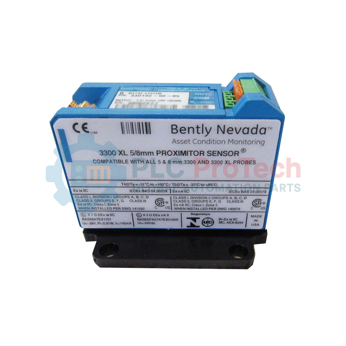
Engineered for highly reliable proximity measurement within machine protection systems, the Bently Nevada 143416-01 processes eddy current signals from a 3300 XL 5mm or 8mm probe to deliver precise vibration and position telemetry. This high-precision sensor acts as a key signal conditioner, generating an analog voltage output directly proportional to the static or dynamic distance between the probe tip and the target shaft. Specifically calibrated for a 5.0-meter system length, the Bently Nevada 143416-01 ensures continuous, uninterrupted monitoring of critical rotating machinery in demanding industrial environments.
Features
- Fully compatible with 3300 XL 5mm and 8mm proximity probes and extension cables.
- Calibrated for a total physical system length of 5.0 meters to ensure accurate electrical scale factor output.
- Robust resistance against radio frequency interference (RFI) and electromagnetic noise.
- Provides a stable, high-fidelity linear output voltage relative to physical target gap variations.
- Compact, durable package designed for standard DIN rail or high-density panel mounting.
Applications
- Radial vibration and axial position monitoring of steam, gas, and hydro turbines.
- Eccentricity and speed measurement on critical power generation machinery.
- Shaft displacement tracking in high-speed industrial compressors and turboexpanders.
- Rotor dynamics diagnostics in harsh chemical and petroleum processing plants.
Technical Specifications
| Parameter |
Specification Value |
| Manufacturer |
Bently Nevada (Baker Hughes) |
| Model Number |
143416-01 |
| Product Series |
3300 XL |
| Compatible Probes |
3300 XL 5mm and 8mm Proximity Probes |
| System Length Calibration |
5.0 Meters |
| Scale Factor |
7.87 V/mm (200 mV/mil) Nominal |
| Supply Voltage Requirements |
-24 Vdc (Acceptable input range: -18 Vdc to -26 Vdc) |
| Current Consumption |
Less than 12 mA (Nominal) |
| Output Impedance |
50 ohms |
| Operating Temperature |
-51 degC to +100 degC (-60 degF to +212 degF) |
| Storage Temperature |
-51 degC to +105 degC (-60 degF to +221 degF) |
| Country of Origin |
United States |
| Shipping Weight (Calculated) |
0.25 kg (0.55 lbs) |
| Package Dimensions (Calculated) |
12.0 cm x 10.0 cm x 6.0 cm |
Connections and Interfaces
| Terminal / Connector |
Function / Circuit Assignment |
| PROBE Coaxial Port |
Accepts subminiature coaxial connection from the 3300 XL extension cable. |
| VT Terminal |
Power Input (-24 Vdc supply connection relative to COM). |
| OUT Terminal |
Dynamic Analog Voltage Signal Output (proportional to target distance). |
| COM Terminal |
Common Ground Reference for power supply and signal return. |
Empirical Engineering Insights
Alternative Models & Compatibility: The 143416-01 is explicitly tuned to a 5.0-meter system length. If your loop utilizes a 9.0-meter probe and extension cable arrangement, utilizing this sensor will severely skew output voltage calculations, requiring substitution with a 9.0-meter variant. Never mix 3300 XL series components with obsolete 7200 series sensors as impedance mismatches will compromise safety shutdowns.
Application Pitfalls & Engineering Notes: Because eddy current technology relies on the electromagnetic properties of the target material, any deviation from standard AISI 4140 steel targets requires custom calibration of the Proximitor to prevent major measurement errors. Always mount the unit within a secure weather-proof or explosion-proof enclosure if located near process streams to avoid housing erosion from corrosive gases.
Commissioning & Wiring Tips: Ensure the coaxial connection is fully tightened using only hand torque; over-tightening with hand tools can fracture the internal subminiature connector. For electrical noise isolation, wrap the coaxial connection boot with self-amalgamating insulation tape to prevent accidental shorting or grounding against adjacent conduit runs.
Installation Guidelines
CRITICAL WARNING: De-energize all connected power sources, monitoring racks, and adjacent high-voltage field devices before proceeding with physical or electrical installation. Verify zero voltage presence at the terminal block using a calibrated digital multimeter. Failure to follow industrial safety, lockout, and tagout protocols can lead to machine protection trips or system hardware damage.
1
Mount the 143416-01 Proximitor housing securely inside the instrument enclosure using standard 35mm DIN rail or direct panel mounting holes. Ensure proper physical clearance for clean routing of the probe cable and signal terminal connections.
2
Connect the 3300 XL extension cable to the Proximitor coaxial port. Route the field cable cleanly, observing the minimum bending radius of 25.4mm (1.0 in) to prevent internal physical degradation of the coaxial core.
3
Strip the signal field wiring (recommended 18 to 22 AWG shielded, twisted-pair wire) and connect to VT (-24 Vdc), OUT (Output signal), and COM (Common) terminals. Ensure the field wire shield is terminated only at the safety monitoring system or barrier ground.
4
Energize the loop and use a multimeter to measure the gap voltage between the COM and OUT terminals, adjusting probe depth in the machine bracket to verify the target is within the linear voltage range of the sensor.