Description
Executing continuous machinery protection functions within the 3500 rack system, the Bently Nevada 176449-01+125680-01 pairs a four-channel 3500/40M Proximitor Monitor with a 125680-01 internal termination I/O module. This combination processes high-frequency inputs from proximity transducers to provide precise measurements of radial vibration, thrust position, eccentricity, and differential expansion. By embedding terminal connections directly onto the 125680-01 I/O card, the assembly eliminates the need for external terminal blocks, reducing cabinet footprint and simplifying complex field wiring in demanding environments.
Features
-
Four-Channel Architecture: Independent channel configuration supports simultaneous tracking of radial vibration, axial thrust, and shaft position.
-
Internal Terminations: The 125680-01 backplane card incorporates dedicated termination blocks directly on the module, streamlining loop wiring.
-
On-Board Signal Conditioning: Integrates high-accuracy analog-to-digital conversion and dynamic signal processing to calculate peak-to-peak and average values.
-
Flexible Alarm Profiles: Independent configuration of Alert and Danger thresholds for each channel with selectable time delays.
-
Comprehensive System Diagnostics: Continuous monitoring of transducer circuits, power supplies, and internal operations to trigger instant OK relay status transitions.
Applications
- Steam and gas turbine bearing housing vibration and rotor position monitoring.
- High-pressure centrifugal compressor rotor dynamic analysis.
- Industrial gearbox, blower, and heavy-duty fan vibration tracking.
- Critical rotating machinery protection in oil and gas, power generation, and petrochemical processing.
Technical Specifications
| Parameter |
Specification Value |
| Manufacturer |
Bently Nevada |
| Monitor Module Part Number |
176449-01 (3500/40M) |
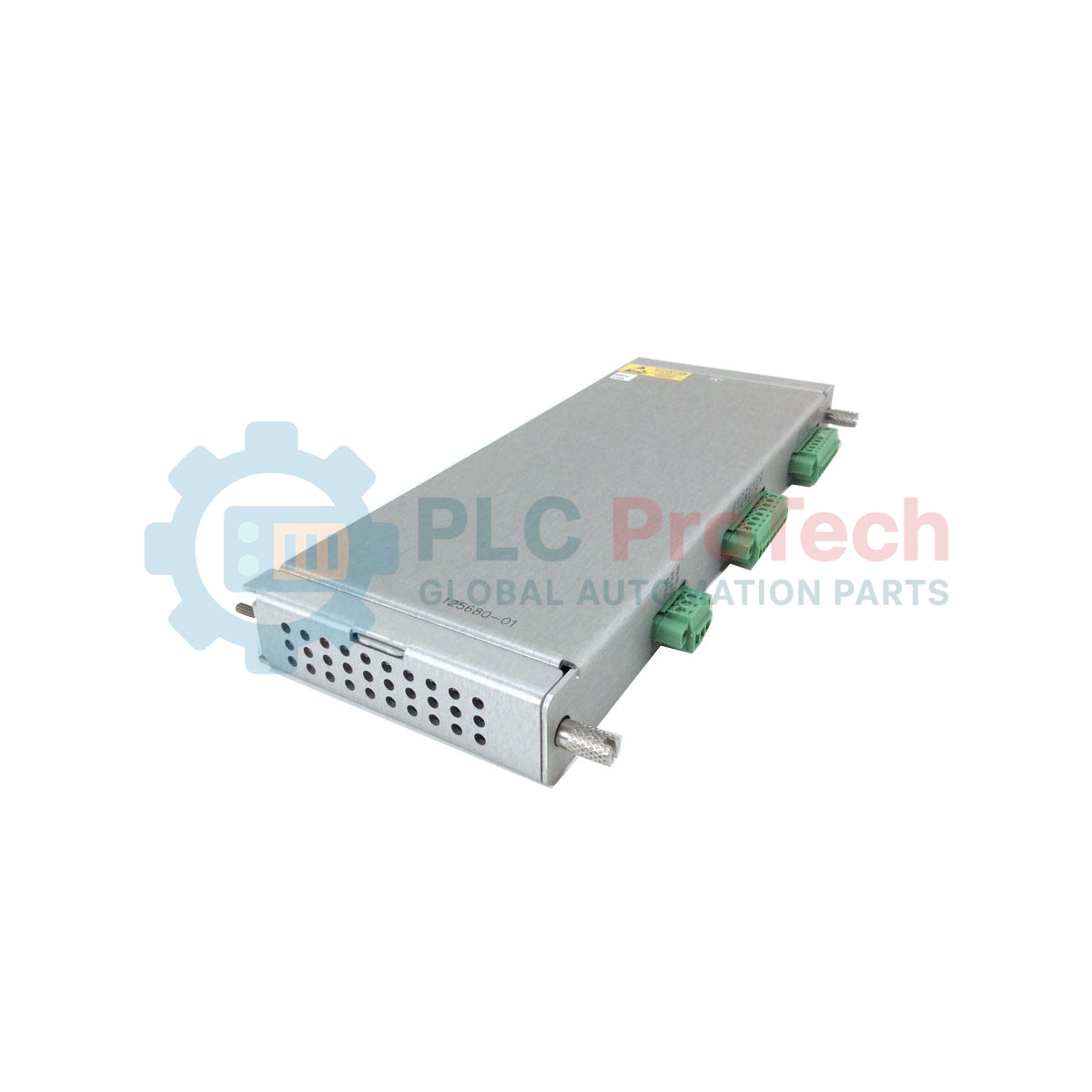
| I/O Module Part Number |
125680-01 (Internal Terminations) |
| System Compatibility |
Bently Nevada 3500 Monitoring System |
| Number of Channels |
4 independent channels |
| Input Transducer Support |
Proximitor Transducers (including 3300 XL series) |
| Signal Range |
-24 VDC nominal loop supply; standard proximity probe outputs |
| Termination Type |
Internal Terminal Strips (Screw-clamp) |
| Operating Temperature |
-30 to +65 degC |
| Country of Origin |
United States of America (USA) |
| Shipping Weight |
10.0 kg (including packaging and modules) |
Connections and Interfaces
| Terminal Block Label |
Signal Assignment / Function |
| Ch 1 PROX / COM / SIG |
Channel 1 Transducer Power, Ground, and Signal Return |
| Ch 2 PROX / COM / SIG |
Channel 2 Transducer Power, Ground, and Signal Return |
| Ch 3 PROX / COM / SIG |
Channel 3 Transducer Power, Ground, and Signal Return |
| Ch 4 PROX / COM / SIG |
Channel 4 Transducer Power, Ground, and Signal Return |
| SHLD Terminals |
Common instrumentation shield ground points (isolated from chassis) |
Alternative Models & Compatibility
The 125680-01 I/O module utilizes screw-type internal terminals, making it mechanically incompatible with racks configured for external termination blocks (which utilize different cable assemblies and the 125680-02 external termination I/O). When hot-swapping or replacing older 3500/40 units, ensure the firmware revision of the 176449-01 matches the version programmed in your 3500 Rack Configuration software to prevent slot mismatch errors and module inhibit states.
Application Pitfalls & Engineering Notes
Because internal termination cables attach directly to the 125680-01 card at the rear of the rack, direct mechanical stress is placed on the card's backplane connector. Implement robust wire-tie and cable tray strain reliefs within the panel to decouple external weight. Ensure the total load on the -24 VDC transducer power loop does not exceed the system specifications when using non-standard extension cables or custom-length proximity sensor runs.
Commissioning & Wiring Tips
Always ground the sensor cable shields at the dedicated SHLD terminals on the 125680-01 module. Never ground the shield at both ends, as this introduces ground loops that corrupt low-voltage proximity measurements with 50/60 Hz industrial noise. Prior to active commissioning, verify that the configured transducer scale factor (e.g., 7.87 V/mm / 200 mV/mil) aligns precisely with the calibrated scale factor of the installed Proximitor sensor.
Installation Guidelines
CRITICAL WARNING: SAFETY FIRST
De-energize the entire 3500 rack system prior to inserting or removing the 125680-01 I/O card. Hot-swapping backplane components under load risks transient electrical faults that can trigger false machinery trip commands. Ground yourself via an ESD wrist strap during the installation procedure.
1
Insert the 176449-01 monitor module into the chosen slot on the front of the 3500 rack. Ensure the ejector tabs lock firmly into position.
2
Align the 125680-01 internal termination I/O module with the matching rear slot guide rails and push firmly until the board seats fully into the backplane connector. Tighten the rear thumbscrews.
3
Connect the field wires to the internal screw terminals, securing the shield drain wire to the designated SHLD terminal for each respective channel.
4
Apply system power, establish connection with the 3500 Rack Configuration Software, upload the correct slot profile, and perform a loop check across all active transducer channels.