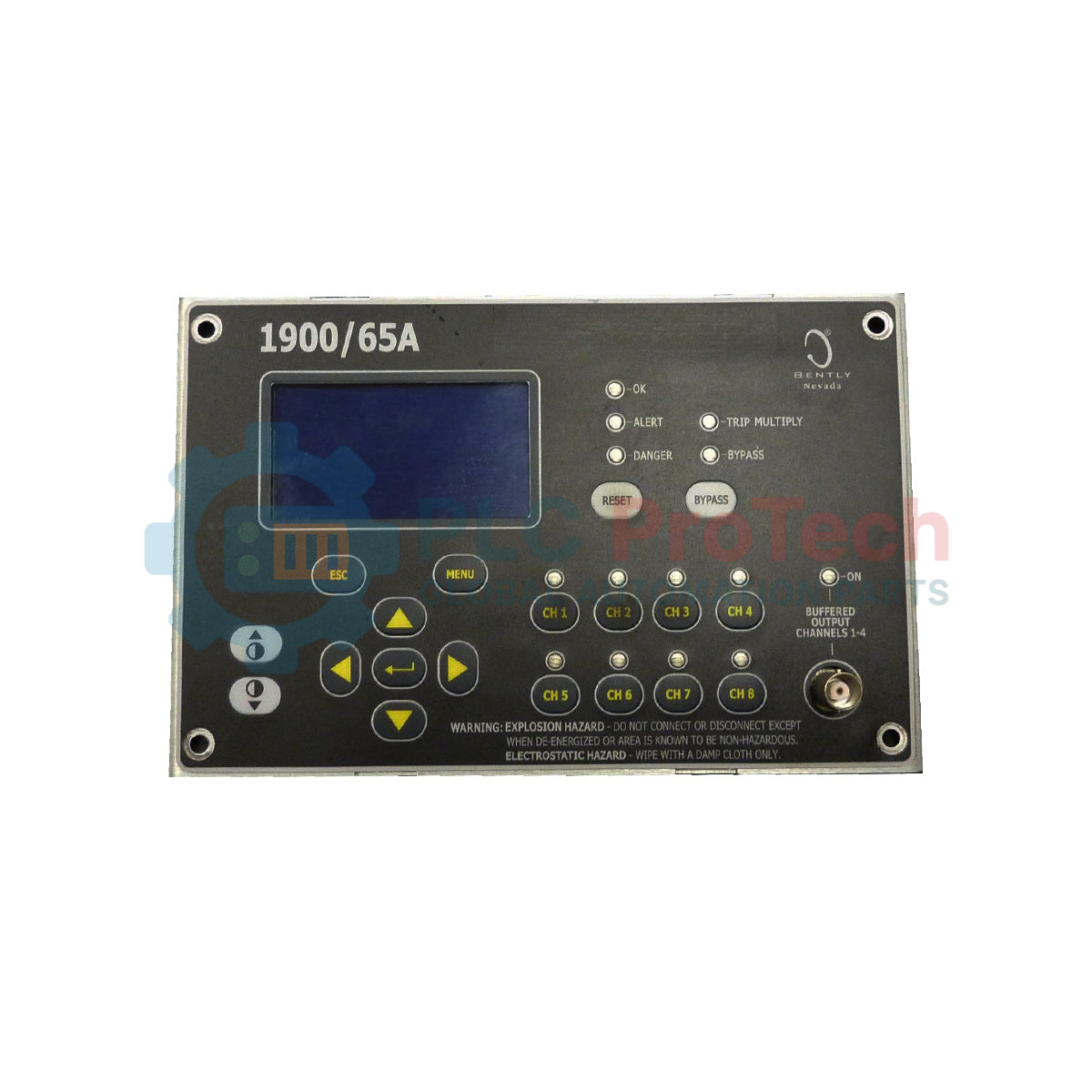
Description
To deliver continuous machinery protection in space-constrained panels, the Bently Nevada 1900/65A-00-00-01-CN-00 functions as a standalone, micro-processor-based vibration and temperature monitoring system. This industrial unit processes inputs from dynamic transducers—such as proximity probes, velocity sensors, and accelerometers—alongside thermal sensor inputs, providing real-time alarm and shutdown capabilities for critical auxiliary machinery. Engineered for remote and decentralized mounting, this headless variant operates without an integrated physical display, instead routing critical status and process data through onboard relays and dynamic buffered outputs.
Features
-
Four Dynamic Channels: Configurable to accept standard vibration, position, and speed transducers.
-
Two Static Temperature Channels: Direct support for RTD and Thermocouple sensors to assess thermal stress on bearings and casings.
-
DIN Rail Mounting (Option 01): Standardized 35mm DIN rail mounting interface for secure mechanical integration into local junction boxes.
-
Headless Operations (Option 00): Omits the physical display panel to prevent unauthorized field adjustments and save cabinet depth.
-
Wide Range DC Input (Option 00): Operates reliably on stable 18 to 36 Vdc industrial distribution loops.
-
Integrated Alarm Logic: Built-in configurable SPDT relays for direct hardware trip-loop wiring.
Applications
-
Electric Motors & Generators: Continuous casing and bearing vibration tracking with winding temperature cross-referencing.
-
Centrifugal & Lobe Blowers: Surge and mechanical imbalance detection in chemical processing environments.
-
Industrial Water Pumps: Localized protection arrays for high-flow cooling and distribution systems.
-
Cooling Tower Fans: Decentralized monitoring inside hazardous wet areas utilizing local protective enclosures.
Technical Specifications
| Parameter |
Specification Value |
| Manufacturer |
Bently Nevada (Baker Hughes) |
| Model Code |
1900/65A-00-00-01-CN-00 |
| Power Input Option |
18 to 36 Vdc (Option 00) |
| Local Display Option |
No Display (Option 00) |
| Mounting Configuration |
35mm DIN Rail Mount (Option 01) |
| Agency Approvals |
CN / China Region-Specific Certification (Option CN) |
| Communications |
None Installed (Option 00) |
| Dynamic Signal Channels |
4 channels (acceleration, velocity, or proximity) |
| Static Input Channels |
2 channels (RTD/Thermocouple or static voltage inputs) |
| Onboard Relays |
6 Programmable SPDT dry contacts |
| Operating Temperature |
-20 to +70 Celsius |
| Country of Origin |
United States (U.S.A.) |
| Shipping Weight (Calculated) |
8.00 kg |
| Package Dimensions (Calculated) |
320 mm x 250 mm x 190 mm |
Connections and Interfaces
| Terminal / Port Block |
Signal / Circuit Assignment |
| Power Input Terminals |
24 Vdc (+) / Common (-) / Chassis Earth Ground |
| Dynamic Channels (1-4) |
Sensor Excitation Power, Signal Return, and Instrument Common |
| Static Channels (5-6) |
RTD Constant Current Source, Return, Shield, and Thermocouple Compensation |
| Relay Contact Blocks |
Normally Open (NO), Normally Closed (NC), and Common (COM) for dry loops |
| Buffered Outputs |
Dedicated raw waveform outputs for direct connection to diagnostic analyzers |
Empirical Engineering Insights
Alternative Models & Compatibility
The 1900/65A series provides local machinery shutdown loop execution faster than a centralized 3500 rack system, acting as an autonomous safety interlock. Be aware that the display option '00' is physically incompatible with external display retrofits without full motherboard upgrades. When swapping units, verify the device's local internal configuration maps directly with the existing transducer scale factors via the configuration utility.
Application Pitfalls & Engineering Notes
Because this variant utilizes an 18 to 36 Vdc input range, supply electrical noise can couple into the high-frequency measurement circuits. Ensure you use an isolated, clean instrument-grade power supply to avoid false high-vibration alarms. Additionally, the blind front panel configuration means maintenance teams must use the programming interface to perform manual alarm resets if latching relays are selected in the software.
Commissioning & Wiring Tips
Ensure sensor cable shields are terminated at the monitor end only. Floating the shield at the transducer avoids forming localized ground loops that introduce mock signals at 50Hz or 60Hz. Verify proper installation orientation on the DIN rail to allow natural thermal convection across the aluminum heat dissipation casing.
Installation Guidelines
CRITICAL WARNING:
DE-ENERGIZE all input electrical lines before installing or removing terminal connections. Failure to follow safe isolating procedures can result in terminal damage, arc flash occurrences, or complete system component failure.
1
Snap the monitor onto the standard 35mm DIN rail, ensuring the locking clasp fully engages and stabilizes the housing.
2
Connect the dynamic vibration sensor wires to channels 1 through 4, referencing the specific transducer scale factor.
3
Perform shield grounding termination on the common bus rail immediately adjacent to the terminal block entry points.
4
Connect the 24 Vdc power input line, energize the source, and check status LEDs to confirm initial initialization behavior is nominal.