Description
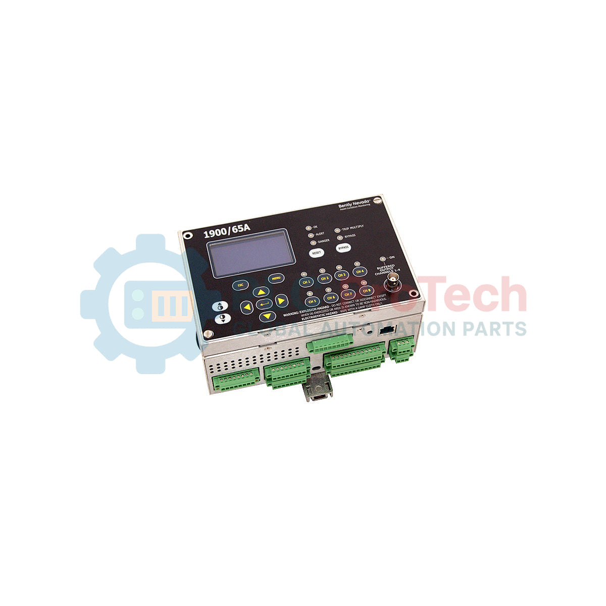
Providing dedicated, continuous machine-level machinery protection, the Bently Nevada 1900/65A-00-00-03-00-00 functions as a rugged, standalone four-channel monitor configured for critical machinery parameters such as vibration, temperature, position, and speed. The 1900/65A series architecture integrates transducer conditioning, alarm detection, and output relays into a single, compact system. This specific variation operates on 18 to 36 Vdc power, features no local display for streamlined remote control configurations, and is safely housed inside a weatherproof Fiberglass NEMA 4X/IP66 enclosure with a clear viewing window. By combining dynamic dynamic-channel processing with static temperature inputs, it reliably monitors cooling towers, small pumps, and industrial fans without requiring a larger rack-based DCS framework.
Features
- Four dynamic input channels compatible with acceleration, velocity, or proximity sensors.
- Two dedicated temperature channels accepting 3-wire RTD or Type E, J, K, and T thermocouples.
- Six configurable relay outputs (four SPDT alarm relays and two system-status relays) for direct equipment trip control.
- Four 4-20 mA analog outputs providing continuous telemetry data to external PLCs or SCADA platforms.
- NEMA 4X/IP66-rated fiberglass housing with a transparent door window for field monitoring in harsh environments.
- No display configuration reduces auxiliary power requirements and prevents unauthorized field tampering.
Applications
- Cooling tower fan gearboxes and structural vibration monitoring.
- Industrial air compressors and processing blowers.
- Electric motors, centrifugal pumps, and secondary water circulation loops.
- Small-scale steam and gas turbines in cogeneration plants.
Ordering Information
| Option Code |
Option Type |
Configuration Detail |
| 1900/65A |
Base Model |
General Purpose Equipment Monitor |
| 00 |
Power Option |
18 to 36 Vdc |
| 00 |
Display Option |
No local display unit |
| 03 |
Mounting Option |
Fiberglass NEMA 4X/IP66 WP housing with window in door |
| 00 |
Approvals Option |
No hazardous area approvals |
| 00 |
Communications |
None (Standard Analog/Relay Interface Only) |
Technical Specifications
| Parameter |
Specification value |
| Supply Voltage Range |
18 to 36 Vdc (24 Vdc nominal) |
| Power Consumption |
3.0 Watts typical, 8.0 Watts maximum |
| Dynamic Signal Inputs |
4 channels, supports Proximitor, Accelerometers, and Velomitors |
| Temperature Inputs |
2 channels, RTD (3-wire 100 ohm Platinum) or Thermocouples (E, J, K, T) |
| Relay Outputs |
4 programmable alarm relays, 2 system status relays (SPDT, 5 A at 250 Vac) |
| Analog Recorder Outputs |
Four 4 to 20 mA outputs (internally powered, max loop resistance 600 ohms) |
| Frequency Response |
0.2 Hz to 20,000 Hz (sensor dependent) |
| Enclosure Classification |
NEMA 4X / IP66 Weatherproof |
| Operating Temperature |
-20 to +70 degC (-4 to +158 degF) |
| Net Weight |
0.77 kg (1.7 lbs) (excluding enclosure) |
| Shipping Weight (Calculated) |
2.00 kg (4.4 lbs) |
| Package Dimensions (Calculated) |
320 mm x 240 mm x 180 mm |
| Manufacturer |
Bently Nevada (Baker Hughes) |
| Country of Origin |
United States |
Connections and Interfaces
| Terminal Block |
Pin / Designation |
Function / Circuit Assignment |
| TB1 |
Power (+), Power (-), GND |
18-36 Vdc Power Connection & Chassis Ground |
| TB2 |
Ch 1 & Ch 2 (+ / - / S) |
Dynamic Transducer Inputs (Proximity / Accelerometers) |
| TB3 |
Ch 3 & Ch 4 (+ / - / S) |
Dynamic Transducer Inputs (Proximity / Accelerometers) |
| TB4 |
A, B, C (Ch 5 & Ch 6) |
RTD Leads or Thermocouple Cold Junction Inputs |
| TB5 |
Relay 1 to Relay 4 |
SPDT Dry Contact Alarm Interlocks |
Empirical Engineering Insights
Alternative Models & Compatibility
The 1900/65A series directly replaces the older legacy 1900/65 platforms. However, configuration files created under the non-A version cannot always be uploaded directly without validation. Ensure you run Bently Nevada Configuration Software Version 1.4 or higher to translate older configuration profiles into the 1900/65A firmware structure.
Application Pitfalls & Engineering Notes
Because this model features the 00 (No Display) option, local physical troubleshooting is restricted to internal LED status indicators. For remote locations, configure the four 4-20 mA outputs to stream directly to a control room DCS to track individual sensor health and prevent blind operation. Additionally, ensure the internal NEMA 4X housing temperature does not consistently exceed 70 degC when switching inductive relay loads at maximum current limits.
Commissioning & Wiring Tips
Always isolate dynamic signal shields from structural earth at the machine end. Sensor shields must terminate strictly at the monitor's TB2 and TB3 shield contacts. Running a single-point ground layout back to the central DC common minimizes high-frequency electromagnetic noise from variable-frequency drives (VFDs) that could otherwise trigger false dynamic alerts.
Installation Guidelines
CRITICAL WARNING: Ensure all primary and auxiliary DC power sources are completely de-energized and locked out before removing the fiberglass cover or inserting wire connections. Verify that any high-voltage relay loads are fully isolated to prevent high-voltage arcing across adjacent terminals.
1
Mount the NEMA 4X fiberglass enclosure securely to a rigid, vibration-free surface using standard mounting hardware to prevent auxiliary structural vibration from corrupting dynamic channel signals.
2
Route dynamic sensor cables and power cables through separate conduit entries to avoid cross-coupling noise on sensitive transducer circuits.
3
Terminate the 18 to 36 Vdc power feeds on terminal block TB1, observing correct polarity to prevent trigger startup failure or protection loop faults.
4
Connect your configuration computer to the internal serial port using the dedicated Bently Nevada programming interface to program sensor scales, trip limits, and dynamic filtering configurations.