Description
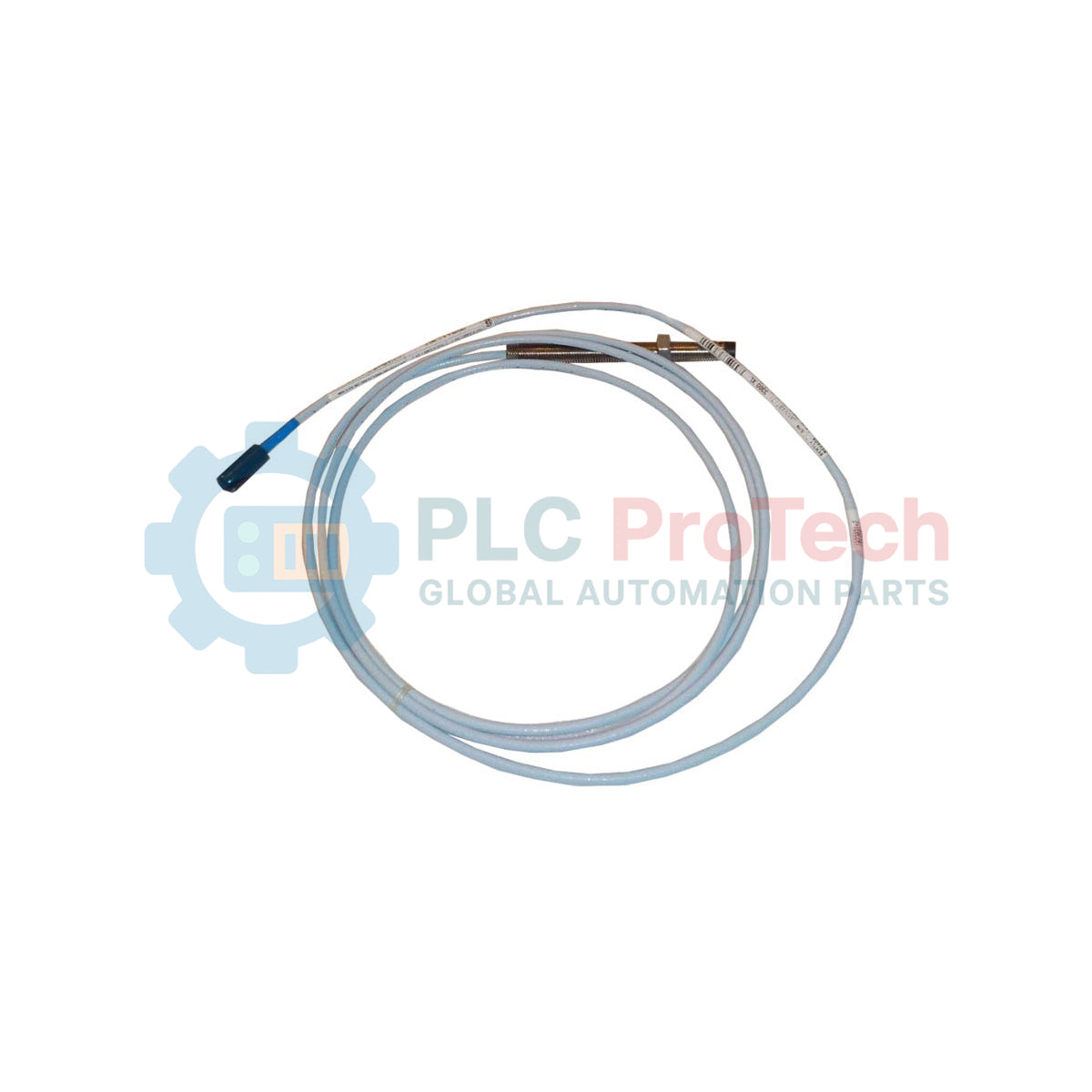
Operational machinery monitoring systems rely on the Bently Nevada 330101-00-35-20-02-CN to provide precise, non-contact shaft vibration and displacement measurements within demanding industrial environments. This 3300 XL 8 mm Proximity Probe features a 3/8-24 UNF threaded design, engineered to interface seamlessly with modern turbomachinery protection systems. With its robust construction, including an AISI 303 or 304 stainless steel case and a Polyphenylene sulfide tip, it ensures long-term calibration stability and physical durability under extreme thermal and chemical exposure.
Key Features
-
High-Performance Tip: Crafted from Polyphenylene sulfide (PPS) for advanced chemical and moisture resistance.
-
ClickLoc Connector: Standard miniature coaxial ClickLoc connector (02 option) prevents accidental disconnection and simplifies field wiring.
-
Robust Enclosure: Corrosion-resistant AISI 303/304 stainless steel case suitable for hazardous environments.
-
Standard Cable Length: 2.0-meter (6.6 feet) cable optimized for common turbine and compressor configurations.
Applications
- Radial vibration and axial position measurements in steam and gas turbines.
- Casing expansion and shaft displacement monitoring in high-speed compressors.
- Hydroelectric generator shaft alignment and orbit analysis.
- Balance-of-plant rotating machinery protection.
Technical Specifications
| Parameter |
Specification Value |
| Manufacturer |
Bently Nevada |
| Model Number |
330101-00-35-20-02-CN |
| Probe Series |
3300 XL 8 mm |
| Unthreaded Length |
0.0 inches |
| Overall Case Length |
3.5 inches |
| Total Length |
2.0 meters (6.6 feet) |
| Connector / Cable Type |
Miniature coaxial ClickLoc connector, standard cable |
| Agency Approval |
CN (Country Specific Approvals) |
| Probe Tip Material |
Polyphenylene sulfide (PPS) |
| Probe Case Material |
AISI 303 or 304 stainless steel (SST) |
| Country of Origin |
United States (USA) |
| Shipping Weight (Calculated) |
1.5 kg (3.3 lbs) |
Empirical Engineering Insights
Alternative Models & Compatibility
The 3300 XL 8 mm system is backward compatible with legacy non-XL 3300 5 mm and 8 mm components. However, always ensure the total physical system length (probe plus extension cable) matches the exact calibration profile of the Proximitor sensor (either 5.0 meters or 9.0 meters). Standardizing on 3300 XL components across the loop reduces thermal drift and guarantees a more linear response over the entire 80 mil (2.0 mm) measurement range.
Application Pitfalls & Engineering Notes
When designing mounting brackets, avoid routing cables through areas containing high-voltage transients. The coaxial signal is sensitive to external electromagnetic interference. Ensure that the probe tip has at least 1.5 times the probe diameter of clear metal target area. Side-loading, or placing the probe too close to structural shoulders or shaft collars, will degrade calibration accuracy and introduce non-linearities into your DCS or TSI system.
Commissioning & Wiring Tips
During installation, perform both a physical gap check and an electrical voltage loop verification. Securely tighten the ClickLoc connectors by hand until they click; do not use pliers, which can deform the miniature coaxial interface. While commissioning, check the Proximitor output voltage. Set the probe gap to register approximately -10.0 V DC (the mid-point of the linear range) to ensure maximum dynamic headroom for both positive and negative shaft movements.
Installation Guidelines
CRITICAL WARNING: SAFETY FIRST
Isolate and lock out all machinery prior to installing or adjusting proximity probes. Do not enter the bearing housing or casing while the shaft is rotating. Ensure all local intrinsic safety or explosion-proof wiring practices are fully adhered to, particularly for units bearing the CN country-specific hazardous area options.
1
Mount the probe bracket securely inside or outside the bearing housing, ensuring alignment with the center-line of the shaft target area.
2
Thread the probe into the bracket while monitoring the gap distance using physical feeler gauges or by reading the voltage output on the Proximitor.
3
Lock the jam nut to the required torque specification, taking care not to twist or strain the integrated coaxial cable.
4
Route the coaxial cable through an approved conduit to the local junction box, maintaining minimum bend radius requirements to prevent internal dielectric damage.