Description
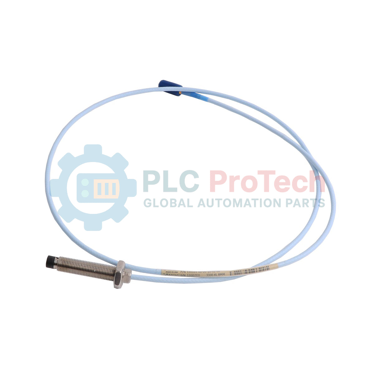
Engineered for continuous industrial vibration and shaft position monitoring, the Bently Nevada 330103-00-18-10-02-00 operates as a core transducer element within the 3300 XL 8mm Proximity Transducer System. This eddy current proximity probe delivers precise, non-contact measurements of static and dynamic shaft movement, making it indispensable for critical machinery protection systems. Its rugged mechanical design is optimized for high-pressure, fluid-film bearing environments typical of heavy rotating machinery.
Features
-
Eddy Current Measurement: Highly accurate non-contact tracking of shaft displacement and vibration.
-
ClickLoc Coaxial Connector: Features a robust, gold-plated miniature coaxial connection designed to resist vibration-induced loosening.
-
Standard Cable Protection: Supplied with durable, high-performance coaxial cabling suitable for standard industrial environments.
-
Thermal Stability: Retains high measurement linearity across broad operating temperature swings.
-
Interchangeability: Fully compatible with standard 3300 XL Proximitor Sensors and extension cables.
Applications
- Steam and gas turbine shaft vibration and axial thrust position tracking.
- Centrifugal compressor radial dynamic motion monitoring.
- Heavy-duty gearbox and industrial pump bearing health assessment.
- Hydroelectric generator shaft runout and alignment verification.
Technical Specifications
| Parameter |
Specification Value |
| Manufacturer |
Bently Nevada (Baker Hughes) |
| Model Series |
3300 XL 8mm Proximity Transducer System |
| Part Number |
330103-00-18-10-02-00 |
| Thread Type |
3/8-24 UNF thread (fractional standard casing) |
| Unthreaded Length |
0.0 inches (0 mm) |
| Overall Case Length |
1.8 inches (180 mm option code) |
| Total Length |
1.0 meter (3.3 feet) |
| Connector and Cable Type |
Miniature coaxial ClickLoc connector, standard cable |
| Agency Approvals |
Not required (Option 00) |
| Operating Temperature Range |
-51 degC to +177 degC (-60 degF to +350 degF) |
| Shipping Weight (Calculated) |
2.0 kg |
Connections and Interfaces
This proximity probe terminates in a miniature gold-plated coaxial ClickLoc connector. It must be paired with a compatible 3300 XL extension cable to interface with the matching 3300 XL Proximitor Sensor.
| Connection Point |
Interface Type |
Function / Shielding |
| Coaxial Center Conductor |
Miniature Coaxial Male |
Carries RF excitation and demodulated displacement signals |
| Coaxial Outer Shield |
ClickLoc Sleeve (Female Outer) |
Provides common return path and continuous EMI shielding |
Empirical Engineering Insights
Alternative Models & Compatibility
Because this probe is a 1.0-meter configuration, it is critical to pair it with a system engineered for the correct total electrical length (typically 5-meter or 9-meter systems). For a standard 5.0-meter calibration loop, this probe requires a 4.0-meter extension cable. Attempting to mix 1.0-meter probes with 9-meter extension cables without proper Proximitor recalibration will introduce severe non-linearity errors in the scale factor.
Application Pitfalls & Engineering Notes
Ensure adequate side clearance during installation. Standard 8mm probes require a minimum of 15.2 mm (0.6 inches) of clearance from adjacent metals. If the probe is mounted too close to a counterbore or bracket, the eddy current field will interact with the surrounding metal, causing false gap voltage readings and flattening the dynamic response curve.
Commissioning & Wiring Tips
Always use a connector protector or self-fusing silicone tape on the ClickLoc connection if the junction is exposed to oil mist or moisture inside the bearing housing. Before final tightening of the mounting nuts, verify the gap voltage using a digital multimeter at the Proximitor's "OUT" and "COM" terminals; a standard gap voltage of approximately -10 VDC corresponds to the midpoint of the linear range.
Installation Guidelines
CRITICAL WARNING
Verify that the machine is completely de-energized and locked out before inserting or adjusting the proximity probe. Ensure that all electrical connections to the monitoring system are powered down to prevent damage to sensitive RF circuitry during probe installation.
1
Mount the probe housing into the threaded bracket. Carefully thread the 3/8-24 UNF casing by hand to avoid cross-threading.
2
Using a calibrated spindle or depth micrometer, set the initial physical gap between the target shaft and the probe tip, aiming for the linear midpoint.
3
Tighten the locknuts to the specified torque rating (not to exceed 11.2 N-m or 100 in-lb) to prevent shift during machine thermal expansion.
4
Route the integrated 1.0-meter cable securely back to the junction box, maintaining a minimum bend radius of 25.4 mm (1.0 inch).