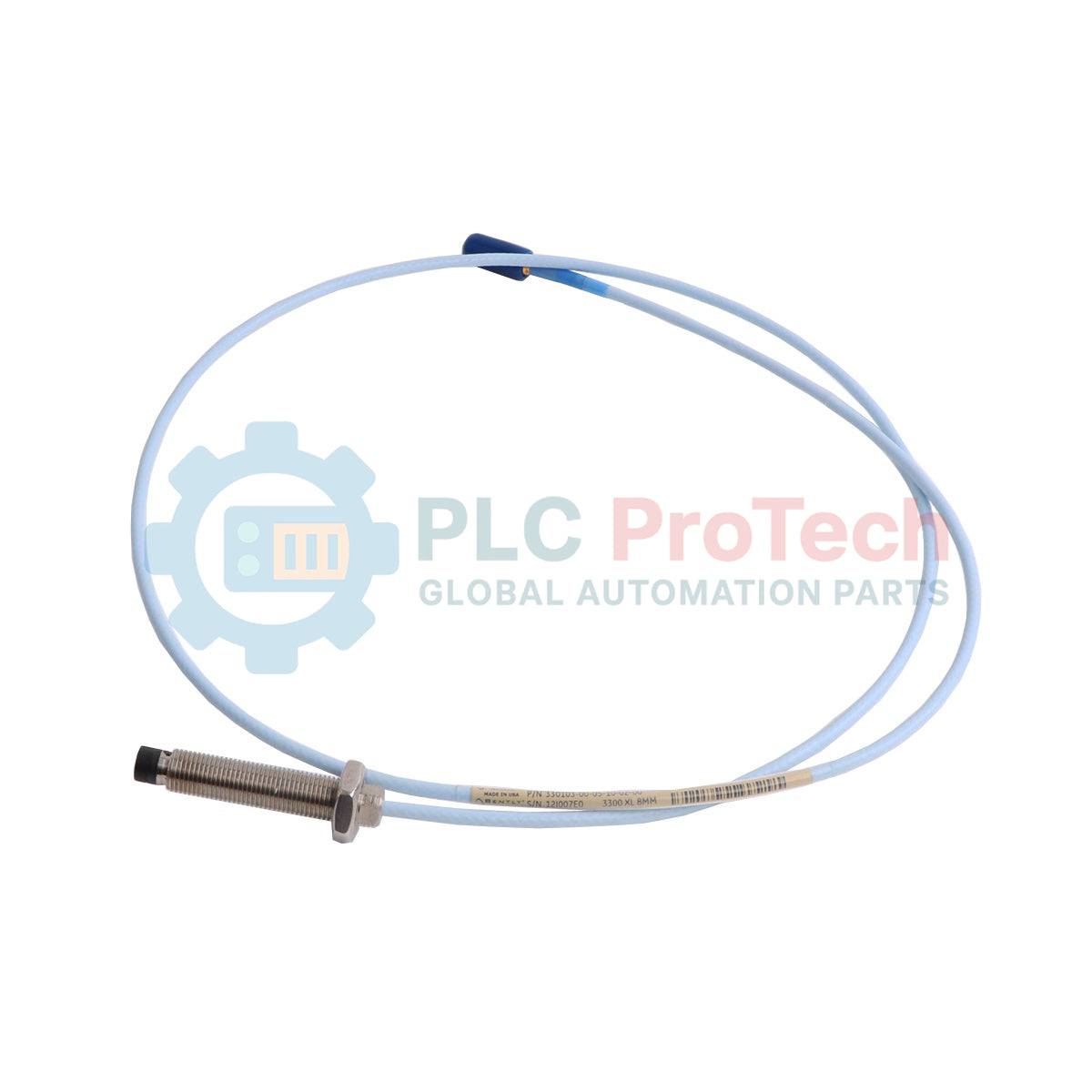
Description
Designed for critical machinery protection systems, the Bently Nevada 330103-06-15-10-02-CN proximity probe provides high-accuracy eddy current measurements of shaft vibration and position. As part of the 3300 XL 8mm Series, this metric-threaded probe utilizes an M10 x 1 thread casing configuration to securely mount into machine housings. This specific variant features a 60mm unthreaded length, a 150mm overall case length, and a 1.0-meter (3.3 feet) total cable length. Equipped with a miniature coaxial ClickLoc connector, the unit guarantees a stable, vibration-resistant connection to the extension cable while carrying country-specific agency approvals for specialized industrial environments.
Features
-
M10 x 1 Threaded Case: Metric mechanical interface engineered for precise insertion depth and thread engagement.
-
ClickLoc Miniature Coaxial Connector: Features a robust locking mechanism that prevents connection degradation in high-vibration environments.
-
8mm Tip Diameter: Optimized for standard linear range measurements up to 2.0 mm (80 mils) when paired with a matching proximitor.
-
High-Temperature Resistance: Constructed with PPS (polyphenylene sulfide) tip material to withstand harsh lubrication environments.
-
Integrated Fluid Seal: Built-in defense against moisture and process fluids migrating through the cable assembly.
Applications
-
Radial Vibration Monitoring: Real-time dynamic tracking of high-speed shafts in steam and gas turbines.
-
Axial Position Detection: Thrust bearing wear monitoring in critical centrifugal compressors and industrial pumps.
-
Eccentricity & Phase Reference: Provides keyphasor signals for diagnostic tracking and rotational speed measurements.
-
Heavy Industrial Environments: Deployed extensively across petrochemical facilities, power generation plants, and gas transmission stations.
Technical Specifications
| Parameter |
Specification Value |
| Manufacturer |
Bently Nevada |
| Model Number |
330103-06-15-10-02-CN |
| Thread Profile |
M10 x 1 (Metric Standard) |
| Unthreaded Length |
60 mm |
| Overall Case Length |
150 mm |
| Total Length Option |
1.0 meter (3.3 feet) |
| Connector and Cable Type |
Miniature coaxial ClickLoc connector, standard cable |
| Agency Approval |
CN (Country-Specific / China Ex Approvals) |
| System Compatibility |
3300 XL 8mm Proximity Transducer System |
| Linear Range |
2.0 mm (80 mils) starting at 0.25 mm (10 mils) from probe face |
| Nominal Scale Factor |
7.87 V/mm (200 mV/mil) |
| Operating Temperature Range |
-51 degC to +177 degC (-60 degF to +350 degF) |
| Net Weight |
0.323 kg |
| Shipping Weight (Calculated) |
1.500 kg |
| Country of Origin |
United States |
Connections and Interfaces
| Physical Interface |
Function / Connection Assignment |
| ClickLoc Coaxial Center Conductor |
Carries high-frequency RF signal for eddy current field generation and return signal path. |
| ClickLoc Coaxial Outer Shield |
Provides RF shielding and system ground reference. Must remain electrically isolated from machine case. |
Empirical Engineering Insights
Alternative Models & Compatibility
The total electrical length of the proximity system must always equal 5.0 or 9.0 meters. Since this probe is a 1.0-meter configuration (Option 10), it must be paired with a 4.0-meter extension cable for 5-meter systems, or an 8.0-meter extension cable for 9-meter systems. Mixing total system lengths will alter the impedance, causing significant calibration errors and invalidating the 200 mV/mil scale factor.
Application Pitfalls & Engineering Notes
When threading the M10 case, avoid over-torquing during installation. The maximum torque rating for M10 threads is 7.5 N-m (66 in-lb). Exceeding this limit risk shearing the case or damaging internal coil lead solder joints. Additionally, maintain a minimum radial clearance of 16 mm (0.63 in) around the probe tip to prevent adjacent metal from causing false target readings (side-viewing error).
Commissioning & Wiring Tips
Always verify the gap using a digital voltmeter measuring the Proximitor OUT terminal. At the target midpoint (typically 1.27 mm or 50 mils gap), the DC output voltage should register approximately -10.0 VDC. Ensure that ClickLoc connectors are insulated from ground using connector protectors or self-fusing silicone tape; grounding the coaxial coupling to the machine housing will introduce signal noise and trigger false machine trips.
Installation Guidelines
CRITICAL WARNING
Ensure the machine is fully shut down and all rotating shafts are stationary before commencing installation. De-energize the monitoring system to prevent voltage spikes. Do not run probe cables adjacent to high-voltage AC lines; maintain separation in dedicated, grounded conduits to avoid electromagnetic interference.
1
Thread the probe into the mounting bracket or machine housing by hand, taking care not to cross-thread the metric M10 x 1 interface.
2
Adjust the physical gap using a spindle micrometer or by monitoring the DC voltage output of the matching proximitor until the target electrical midpoint (-10 VDC) is achieved.
3
Lock the probe body in place using the standard locknuts, applying a maximum torque of 7.5 N-m.
4
Join the miniature ClickLoc connector to the extension cable by pushing firmly until the connection clicks into position, then seal using connector protection sleeves.