Description
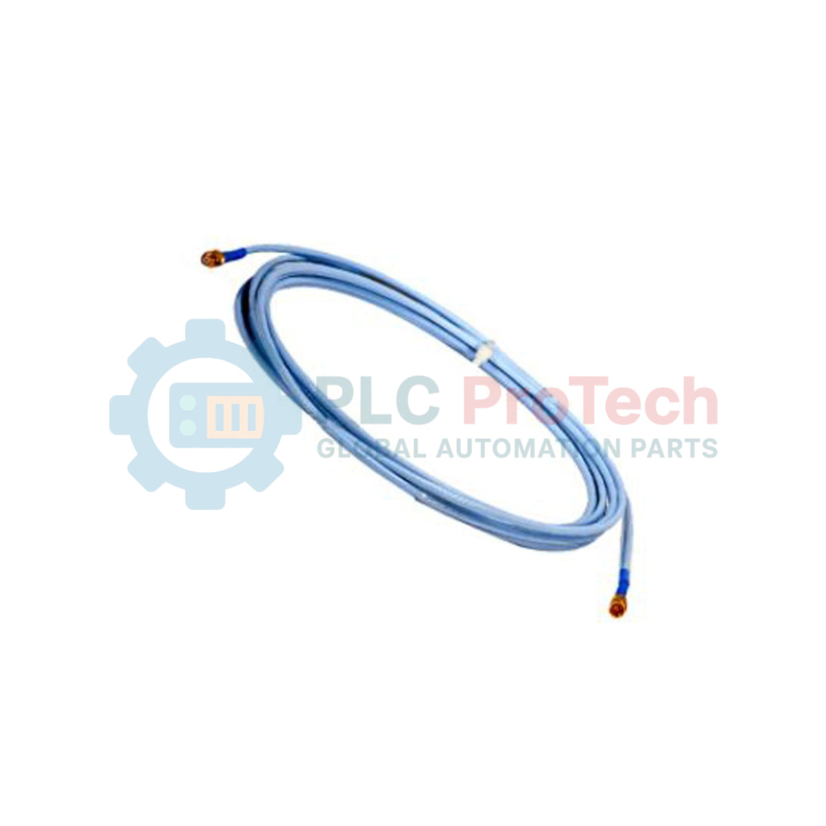
Transmitting critical high-frequency eddy current signals with minimal loss, the Bently Nevada 330130-045-03-CN serves as an indispensable link in machinery protection architectures. This premium extension cable interfaces directly with the 3300 XL 8mm proximity transducer system, delivering precision gap and vibration measurements to industrial monitoring systems. Engineered for harsh industrial environments, this specific model features integrated mechanical armoring and robust connector protection to guarantee signal integrity even when subjected to physical stress or chemical exposure.
Features
-
Integrally Armored Protection: Outfitted with stainless steel armor wrapping to shield the delicate internal coaxial line from mechanical crush hazards, abrasive wear, and cutting forces.
-
Connector Protectors Included: Factory-installed silicone elastomer connector protectors prevent fluid ingress, particulate contamination, and accidental disconnects at critical junction points.
-
Matched Impedance Coaxial Core: Specifically calibrated electrical characteristics prevent signal reflection and maintain phase accuracy across the entire frequency spectrum.
-
Regional Regulatory Compliance: The "CN" designation specifies authorization and documentation compliance tailored to strict national import and hazardous area certifications.
Applications
-
Steam & Gas Turbines: High-reliability radial vibration and axial thrust position monitoring.
-
Centrifugal & Axial Compressors: Shaft dynamics and casing vibration analysis in petrochemical processing plants.
-
Large Boiler Feed Pumps: Continuous health tracking of bearing clearances under high operational pressures.
-
Industrial Generators & Gearboxes: Early fault detection via dynamic proximity measurement inside enclosed machine housings.
Technical Specifications
| Parameter |
Specification |
| Manufacturer |
Bently Nevada |
| Model Number |
330130-045-03-CN |
| System Compatibility |
3300 XL 8mm Proximity Transducer System |
| Cable Length |
4.5 meters (14.8 feet) |
| Armor Option |
Armored cable with connector protectors |
| Approvals Option |
CN (Country-specific hazardous area certifications) |
| Core Type |
Coaxial (75 Ohm nominal impedance) |
| Operating Temperature |
-51 degC to +177 degC (-60 degF to +350 degF) |
| Country of Origin |
United States (U.S.A.) |
| Shipping Weight (Calculated) |
1.50 kg (3.3 lbs) |
Connections and Interfaces
| Connector Port / Side |
Connection Profile |
Protective Hardware |
| Probe Interface (Female) |
Miniature coaxial click-lock socket |
Integrated silicone connector boot |
| Proximitor Interface (Male) |
Miniature coaxial plug pin |
Teflon-insulated sleeve with outer metal protection |
Empirical Engineering Insights
Alternative Models & Compatibility
The 4.5-meter physical cable length is specifically designed to work in conjunction with a 0.5-meter proximity probe to achieve a total calibrated electrical system length of 5.0 meters. Substituting a 9.0-meter system component (such as a 9.0-meter Proximitor sensor) with this 5.0-meter configuration will result in immediate calibration mismatch errors and highly inaccurate scale factor readings. Verify your Proximitor sensor's calibrated system length before deployment.
Application Pitfalls & Engineering Notes
While the armored casing provides extreme protection against mechanical damage, it increases the minimum physical bending radius. Forcing this cable into standard conduit bends tighter than 75 mm can pinch the inner dielectric core, altering the capacitance and degrading the system's overall frequency response. Always design junction boxes and conduit entries with generous sweep bends.
Commissioning & Wiring Tips
Ensure that all coaxial interfaces are perfectly dry and free from grease or cutting oil prior to making the final connection. Use a specialized coaxial connector torque wrench (recommending 0.45 to 0.56 Nm) to avoid over-tightening or stripping the delicate miniature threads, which can introduce intermittent signal noise or micro-disconnections under heavy machinery vibration.
Installation Guidelines
CRITICAL WARNING: De-energize all machinery and verify the proximity sensor driver is completely powered down before connecting or disconnecting the cable. Live mating of coaxial connectors can introduce voltage transients that risk degrading the input amplifiers of the monitor modules or causing false machine trips.
1
Unbox the cable and inspect the integrity of the flexible stainless steel armor and the end connectors for any physical defects or surface contamination.
2
Lay the cable along its designated path, avoiding sharp corners, high-temperature manifolds, and heavy electromagnetic interference (EMI) paths such as variable speed drive power cables.
3
Clean the connectors using a high-grade contact cleaner. Align the male and female coax terminals and thread them together securely. Engage the connector protectors to seal the joint.
4
Secure the armored outer sheath inside robust cable clamps or junction boxes to prevent long-term fatigue failure caused by persistent dynamic cable movement.