Description
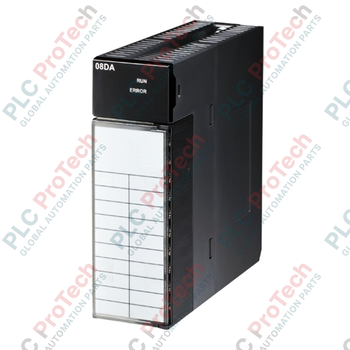
Operating as a high-density digital-to-analog converter within the AH500 platform, the Delta Electronics AH08DA-5C provides precise current loop control for demanding industrial process loops. This 8-channel analog output module delivers 16-bit hardware resolution to ensure fine control granularity over 0 to 20mA and 4 to 20mA signal ranges. Engineered with an isolated signal design, it effectively isolates field-side electrical noise from the backplane, ensuring stable CPU operation. The hardware supports an independent interrupt function, hot-swapping under powered backplanes, and a programmable keep-last-value parameter to maintain safe physical states in the event of a controller stop.
Features
-
High-Density Output: Provides 8 high-precision current output channels in a single rack-space allocation.
-
Advanced Resolution: Features 16-bit hardware D/A conversion for highly granular setpoint adjustments.
-
Hot-Swap Capability: Supports module replacement while the PLC system remains active, reducing overall plant downtime.
-
Signal Isolation: Optically isolated signal design prevents ground loops and safeguards internal logic circuitry.
-
Failsafe Security: Incorporates a configurable keep-last-value state for outputs during CPU shutdown or communication loss.
-
Serviceable Design: Equipped with a removable JIS terminal block to simplify field wiring and hardware upgrades.
Applications
- Proportional control valve positioning and pneumatic actuator modulation.
- Variable Frequency Drive (VFD) speed reference distribution across multi-drive configurations.
- Industrial heater output regulation via thyristor power controllers.
- Tension and flow control loops in paper mills, steel plants, and water treatment facilities.
Technical Specifications
| Specification Parameter |
Technical Value |
| Manufacturer |
Delta Electronics |
| Model |
AH08DA-5C |
| Output Points |
8 channels |
| Signal Ranges |
0 to 20 mA, 4 to 20 mA |
| Hardware Resolution |
16-bit |
| Conversion Speed |
150 us per channel |
| Internal Power Consumption |
0.25 W |
| External Power Consumption |
3.7 W (24 VDC nominal) |
| Base Error (Ambient Temp) |
Current mode +/-0.06% |
| Base Error (Full Temp Range) |
Current mode +/-0.07% |
| Linearity Error (Ambient Temp) |
Current mode +/-0.01% |
| Linearity Error (Full Temp Range) |
Current mode +/-0.01% |
| Terminal Connection |
JIS removable terminal block |
| Isolation |
Optocoupler isolation between digital loop and analog channel |
| Shipping Weight (Calculated) |
2.0 kg |
Empirical Engineering Insights
Alternative Models & Compatibility
This module is designed exclusively for the Delta AH500 high-performance PLC rack architecture. Configuration and channel mapping are managed via Delta ISPSoft software (version 3.0 or higher). If upgrading from legacy hardware, verify that the CPU firmware version supports the hot-swap functionality enabled by the backplane hardware interface.
Application Pitfalls & Engineering Notes
While internal backplane consumption is low (0.25 W), the 3.7 W external power consumption must be drawn from a stable, low-noise 24 VDC power supply. Ensure that voltage drop calculations account for the maximum current load of all 8 channels running at 20 mA simultaneously. Voltage drops below 20.4 VDC at the module terminal block can degrade D/A linearity and cause diagnostic under-voltage system alarms.
Commissioning & Wiring Tips
Always use high-quality twisted, shielded pair cabling for current loop connections. Earth the cable shield exclusively at the cabinet ground entry bar; do not ground both ends of the shield to prevent ground loops. If configure-to-run delays occur, check the module interrupt settings in the HWCONFIG utility of ISPSoft to verify execution priority.
Installation Guidelines
CRITICAL WARNING: De-energize all primary and auxiliary field power sources before inserting or removing any field wiring on the JIS terminal block. While the module supports hot-swapping on the active backplane, hot-plugging live field wiring can cause transient electrical arcs, potentially damaging the sensitive 16-bit analog output stage.
1
Mount the module firmly onto the AH500 series backplane rail, securing the top and bottom latching pins completely.
2
Unlatch and remove the JIS terminal block to complete the current loop wiring at an external workstation, minimizing mechanical stress on the module housing.
3
Connect the external 24 VDC power supply directly to the designated power terminals on the block to run the internal output driver circuits.
4
Reattach the wired JIS terminal block, lock it securely, and apply power. Monitor the LED status indicators to ensure proper system initialization and network configuration.