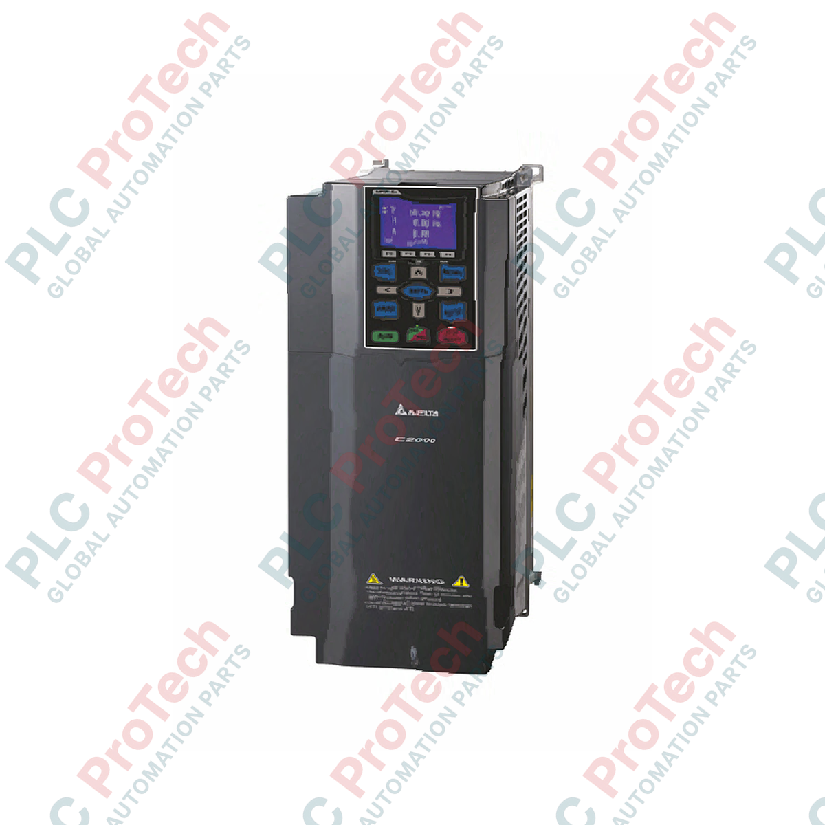
Description
Managing complex motor control configurations requires a dependable power conversion stage, and the Delta Electronics VFD370C43A delivers this through its robust C2000 Series field-oriented control architecture. Engineered for high-performance applications, this 3-phase AC variable frequency drive is configured with a dual-rating structure that allows system integrators to optimize the drive's output based on load profiles. By supporting both Normal Duty (ND) and Heavy Duty (HD) profiles, the module adapts dynamically to variable torque pump/fan configurations or high-overload constant torque machines.
Features
-
Dual-Duty Rating: Seamless transition between Normal Duty (50 HP) and Heavy Duty (40 HP) parameter structures.
-
Flexible Control Methods: Supports advanced sensorless vector control (SVC) and closed-loop field-oriented control (FOC) for exact speed and torque accuracy.
-
Removable Keypad: Standard digital control panel can be detached and mounted remotely via standard connection cables.
-
Adaptable Carrier Frequency: Programmable options up to 10 kHz in Normal Duty or up to 6 kHz in Heavy Duty modes to balance thermal efficiency and low acoustic motor noise.
Applications
- High-capacity industrial water supply systems and circulating pumps.
- Constant-torque machinery including extruders, mixers, and industrial material handling conveyors.
- Exhaust fans, blowers, and automated HVAC air handling units.
Technical Specifications
| Parameter |
Specification Value |
| Manufacturer |
Delta Electronics |
| Model Number |
VFD370C43A |
| Product Series |
C2000 Series |
| Normal Duty Output Capacity |
58 kVA |
| Normal Duty Rated Current |
73 A |
| Normal Duty Motor Rating |
37 kW (50 HP) |
| Normal Duty Frequency Range |
0.00 to 599.00 Hz |
| Normal Duty Carrier Frequency |
2 to 10 kHz (Default: 6 kHz) |
| Heavy Duty Output Capacity |
55 kVA |
| Heavy Duty Rated Current |
69 A |
| Heavy Duty Motor Rating |
30 kW (40 HP) |
| Heavy Duty Frequency Range |
0.00 to 300.00 Hz |
| Heavy Duty Carrier Frequency |
2 to 6 kHz (Default: 2 kHz) |
| Input Phase & Voltage Rating |
3-Phase, 460V AC |
| Physical Dimensions (L x W x H) |
40.5 cm x 25.0 cm x 21.0 cm |
| Product Weight |
27.0 kg |
| Shipping Weight (Calculated) |
28.0 kg |
Empirical Engineering Insights
Alternative Models & Compatibility
The C2000 series is designed to drop-in replace several legacy Delta VFD lines. Note that while control terminal blocks are highly standard, dynamic braking modules are required externally for heavy-duty cyclic stopping. Ensure the drive firmware revision matches any active multi-drive fieldbus communication cards (such as Modbus TCP or EtherNet/IP option cards) to guarantee uniform parameter mapping.
Application Pitfalls & Engineering Notes
When utilizing this drive in environments approaching 50 degrees Celsius, keep a close watch on the active carrier frequency. Running the drive in Normal Duty mode at 10 kHz under maximum continuous load will generate significant heat inside enclosed NEMA/IP20 panels. If thermal over-temperature faults occur, derating the carrier frequency down to 4 kHz or 2 kHz will immediately lower IGBT temperatures without compromising output current performance.
Commissioning & Wiring Tips
To minimize electrical noise injection back into adjacent control or PLC cabinets, always use symmetrically shielded motor cables. Ensure the motor cable shield is bonded to the drive ground plate with 360-degree contact clamps. Do not route analog control signals (e.g., 0-10V or 4-20mA speed references) through the same conduit as the main 460V input/output motor lines.
Installation Guidelines
CRITICAL WARNING: Hazardous voltages remain present in the internal DC bus capacitors even after the mains power supply is disconnected. Wait at least 10 minutes for the internal charge indicators to completely extinguish before removing any covers, handling terminal wiring, or starting physical maintenance work. Verify the DC bus voltage using a calibrated multimeter across terminals (+1) and (-) to confirm it is below 36V DC.
1
Ensure the mounting surface is vertical and solid. Verify that there is at least 150 mm of clear space above and below the drive housing to ensure proper convective cooling and airflow.
2
Terminate the 3-phase AC input lines directly to terminal points R/L1, S/L2, and T/L3. Connect the motor supply cables securely to terminals U/T1, V/T2, and W/T3. Do not connect AC mains power to the motor output terminals under any circumstances.
3
Configure control logic terminal wiring (such as digital inputs or analog references) using shielded twisted-pair cables. Tighten terminal screws to the manufacturer-specified torque limits to avoid connection resistance or loose contacts.