UR-6TH (UR6TH) به عنوان یک ماژول ورودی/خروجی دیجیتال با چگالی بالا طراحی شده برای سری پلتفرم رله یونیورسال GE Vernova Multilin (UR) عمل میکند. این بلوک توسعه سختافزاری مستقیماً در چارچوبهای ماژولار استاندارد UR مانند رلههای حفاظتی F60، L90، G60 و B30 ادغام میشود تا منطق قفل سریع و توزیع تلهمتری را در ایستگاههای فرعی برق و سیستمهای انرژی صنعتی سنگین اجرا کند. این ماژول ترکیبی از ۸ ورودی تماس و ۴ خروجی Form-A را به صورت بهینه برای فرمانهای کنترل با سرعت بالا ارائه میدهد.
خروجیهای دیجیتال Form-A بدون نظارت داخلی تماس عمل میکنند و با استفاده از طراحی مکانیکی پیشرفته، مدت زمان پاسخ کمتر از ۴ میلیثانیه را به دست میآورند. این پروفایل سوئیچینگ فوقالعاده سریع، سختافزار را برای استفاده در مدارهای قطع کلید اصلی که نیازمند قطع فوری قوس و اجرای توالی حفاظتی هستند، بسیار مناسب میسازد. با عملکرد در چارچوب نرمافزاری اصلی رله میزبان، مسیرهای ورودی و خروجی محلی به صورت پویا از طریق لینکهای داخلی بکپلین با استفاده از نرمافزار EnerVista UR Setup مدیریت میشوند تا نگاشت توالی خودکار و کاهش سیمکشی فیزیکی پنل کنترل کمکی را فراهم کنند.
ویژگیها
خروجیهای Form-A با سرعت بالا: مجهز به ۴ تماس Form-A بدون نظارت با سرعت پاسخ بسیار سریع کمتر از ۴ میلیثانیه برای کاربردهای قطع مستقیم کلید.
کسب تماس متراکم: دارای ۸ ورودی تماس مستقل برای ثبت تغییرات وضعیت گسسته از تجهیزات کمکی قدرت.
ادغام برنامهنویسی FlexLogic: نگاشت کامل تمام ۸ ورودی و ۴ خروجی در ویرایشگر داخلی FlexLogic برای اتوماسیون سفارشی، قطع خودکار اضافهبار و طرحهای مسدودسازی خارجی.
کاهش سیمکشی سختافزاری: کاهش قابل توجه زیرساختهای سیمکشی ثانویه پیچیده در داخل پنلهای ایستگاههای فرعی سنتی از طریق تمرکز نقطهای دیجیتال محلی.
سازگاری ولتاژ انعطافپذیر: پشتیبانی از ولتاژهای کنترل DC صنعتی استاندارد از ۲۴ ولت DC تا ۲۵۰ ولت DC بسته به پیکربندی نهایی سیستم.
کاربردها
مدارهای قطع مستقیم کلید اتوماتیک با سرعت بالا (قطع)
شبکههای قفل و سیگنالدهی تجهیزات ایستگاه خودکار.
گسترش نقاط ورودی/خروجی دیجیتال برای رلههای سری Multilin UR (F60، L90، G60، B30).
سیستمهای مدیریت توان صنعتی توزیعشده که نیاز به نگاشت منطق سفارشی دارند.
مشخصات فنی
پارامتر
مشخصات و جزئیات فنی
تولیدکننده
GE Vernova (راهحلهای شبکه / مولتیلین)
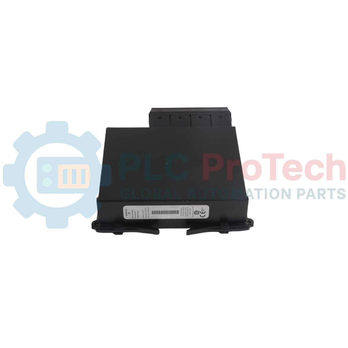
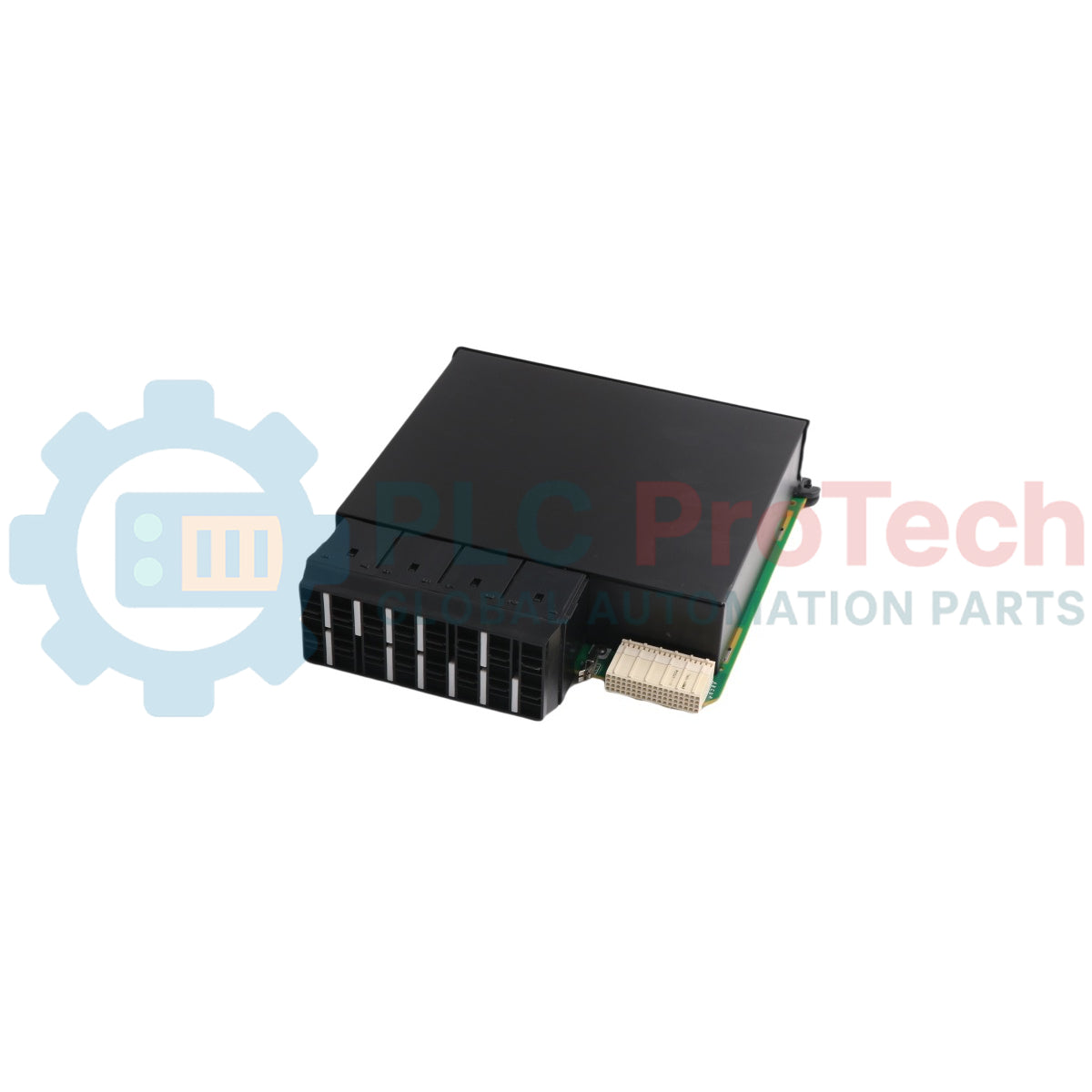
مدل
UR-6TH
نوع ماژول
ماژول ورودی/خروجی دیجیتال (ماژول I/O دیجیتال)
خانواده محصول
سری رله یونیورسال مولتیلین (UR)
کانالهای ورودی
8 ورودی کنتاکت
کانالهای خروجی
4 خروجی فرم-A (بدون نظارت)
سرعت پاسخ خروجی
کمتر از 4 میلیثانیه (پاسخ فوقالعاده سریع)
ولتاژ کنترل نامی
24 ولت DC تا 250 ولت DC (بسته به کد سفارش و پیکربندی)
هنگام تعویض یا ارتقاء کارتهای مدولار در یک سیستم رله فعال، اطمینان حاصل کنید که مشخصات ماژول ورودی/خروجی جدید کاملاً با نسل CPU و نوع شاسی رله میزبان مطابقت دارد. کارتهای ورودی/خروجی رله یونیورسال در ویژگیها به شدت متفاوت هستند، مانند وجود یا عدم وجود نظارت بر کنتاکت. همیشه کد سفارش الفبایی-عددی کامل چاپ شده روی پلاک نام اصلی رله را مقایسه کرده و شکاف فیزیکی کارت هدف (معمولاً شکافهای G، H، M، N، P، U یا W) را قبل از نصب سختافزار تأیید کنید.
ایزولاسیون برق قبل از نصب
منبع تغذیه کمکی اصلی ثانویه AC/DC که به واحد میزبان رله یونیورسال تغذیه میکند را کاملاً قطع کنید.
تمام حلقههای جریان، ولتاژ و قطعکننده مدار خارجی که به ترمینالهای میدانی خارجی متصل هستند را ایزوله یا به صورت مکانیکی قفل کنید تا از فعال شدن تصادفی قطعکننده میدانی در طول فرآیند تعویض جلوگیری شود.
یک بند مچ دست تخلیه الکترواستاتیک (ESD) را محکم ببندید و آن را به زمین فیزیکی تأیید شده متصل کنید تا میکروپروسسورهای داخلی در برابر تخریب ناشی از الکتریسیته ساکن محافظت شوند.
استخراج ماژول معیوب
یک رایانه شخصی را به رله متصل کرده و از طریق نرمافزار EnerVista UR یک پشتیبانگیری کامل از پارامترها انجام دهید و پیکربندی فعلی را به صورت فایل .urs ذخیره کنید.
پیچهای نگهدارنده صفحه جلویی فیزیکی واقع در گوشههای بالایی و پایینی قاب شکاف ورودی/خروجی هدف را با استفاده از پیچگوشتی مناسب شل کنید.
دستههای استخراج یکپارچه سیاه را محکم بگیرید و ماژول را به صورت مستقیم و یکنواخت به سمت بیرون بکشید تا برد از مجموعه باس بکپلین عقب جدا شود.
وارد کردن ماژول جدید UR-6TH
لبههای عمودی جانبی کارت مدار جدید UR-6TH را داخل مسیرهای راهنمای پلاستیکی قالبگیری شده اسلات خالی شاسی قرار دهید.
ماژول را به آرامی در حفره اسلات خالی بلغزانید تا صفحه جلویی بیرونی کاملاً با ماژولهای ساختاری مجاور همسطح شود.
فشار افقی محکم و متمرکز روی لبههای صفحه جلویی اعمال کنید تا اطمینان حاصل شود که کانکتور چندپین عقب کاملاً در پلاگ بکپلین قرار گرفته است.
هر دو پیچ نگهدارنده پنل بالا و پایین را محکم کنید تا پایداری مکانیکی فراهم شده و حلقه زمین شاسی اجباری کامل شود.
راهاندازی پس از نصب
توزیع توان کمکی سیستم را به ماژول توان اصلی شاسی رله دوباره اعمال کنید.
روند خودآزمایی خودکار را از طریق صفحه نمایش کریستال مایع مانیتور کنید؛ تأیید کنید که هیچ هشدار HARDWARE MISMATCH یا پرچم خطای بحرانی اسلات فعال نشده باشد.
از طریق مجموعه نرمافزاری EnerVista متصل شوید، به بخش Status -> Hardware Configuration بروید و تأیید کنید که سیستم بلوک سختافزاری جدید UR-6TH را به درستی شناسایی کرده است قبل از بازگرداندن عملیات زنده به حلقههای قطع ورودی/خروجی خارجی.
سؤالات متداول
چه نوع خاصی از تماسهای سوئیچینگ در کانالهای خروجی ارائه شده است؟
ماژول شامل ۴ خروجی Form-A است که تماسهای تکقطبی-تکپرتاب معمولاً باز (SPST-NO) هستند. این خروجیها بدون اجزای داخلی نظارت بر جریان یا ولتاژ طراحی شدهاند تا سرعت سوئیچینگ را به حداکثر رسانده و تأخیر پاسخ را زیر ۴ میلیثانیه نگه دارند، که آنها را برای مسیردهی خام قطعکنندهها بسیار مناسب میکند.
آیا این ماژول میتواند در هر اسلاتی در قاب رله یونیورسال قرار گیرد؟
خیر، این ماژول باید به طور خاص در فضاهای استاندارد تعیین شده برای ورودی/خروجی دیجیتال قرار گیرد. این فضاها به اسلاتهای G، H، M، N، P، U یا W در معماری استاندارد شاسی رله یونیورسال مربوط میشوند، بسته به نحوه تخصیص کد پیکربندی اولیه شما.
اگر نسل سختافزاری ماژول با قاب رله میزبان مطابقت نداشته باشد، چه اتفاقی میافتد؟
اگر تضاد نسل سختافزاری بین کارت تازه وارد شده و پردازنده یا فرمویر قدیمی بکپلین رخ دهد، صفحه جلویی رله یونیورسال یک نشانگر خطای بحرانی را فعال کرده و وضعیت HARDWARE MISMATCH را ایجاد میکند که اجرای نرمافزار عملیاتی را تا زمانی که ماژولها یکپارچه شوند، قفل میکند.
راهنمای عملی برای جایگزینی ایستگاههای اپراتور بیلی سیمفونی قدیمی که بر روی OpenVMS Alpha اجرا میشوند. این راهنما مقایسهای بین شبیهسازی Alpha، مهاجرت OpenVMS به x86، بازپلتفرمسازی OPC و نوسازی...
دادههای نگهداری و تعمیرات، سفارشهای کاری، سیگنالهای حسگر، تاریخچه داراییها، هزینهها و دانش تکنسین را به هم متصل میکند. استفاده صحیح از آن، برنامهریزی، قابلیت اطمینان، نگهداری پیشبینیشده،...
این مقاله توضیح میدهد که چگونه عملگرهای الکتریکی یکپارچه، مانند سری e-Actuator شرکت SMC، با جایگزینی سیستمهای پنوماتیک و هیدرولیک سنتی، کنترل حرکت صنعتی را متحول میکنند. این مقاله به بهبود دقت...
این مقاله توضیح میدهد که چگونه سیستمهای PLC عملیات ریاضی اصلی مانند جمع، تفریق، ضرب، تقسیم، مدولو و توان را در اتوماسیون صنعتی انجام میدهند. نشان میدهد که چگونه این بلوکهای عملکردی سیگنالهای...
این مقاله چندین تابع پیشرفته منطق بولی را که در برنامهنویسی PLC فراتر از عملیات پایه AND، OR و NOT استفاده میشوند، توضیح میدهد. همچنین نحوه استفاده از ابزارهایی مانند جداول صحت، مالتیپلکسرها،...
منطق بولی پایه و اساس هر برنامه PLC است. از کنترلهای ساده ماشین تا سیستمهای پیچیده اتوماسیون صنعتی، دروازههای منطقی تعیین میکنند که کنترلکنندهها چگونه به ورودیها و شرایط عملیاتی متغیر پاسخ...
انتخاب یک گزینه باعث بارگذاری مجدد کامل صفحه میشود.