Description
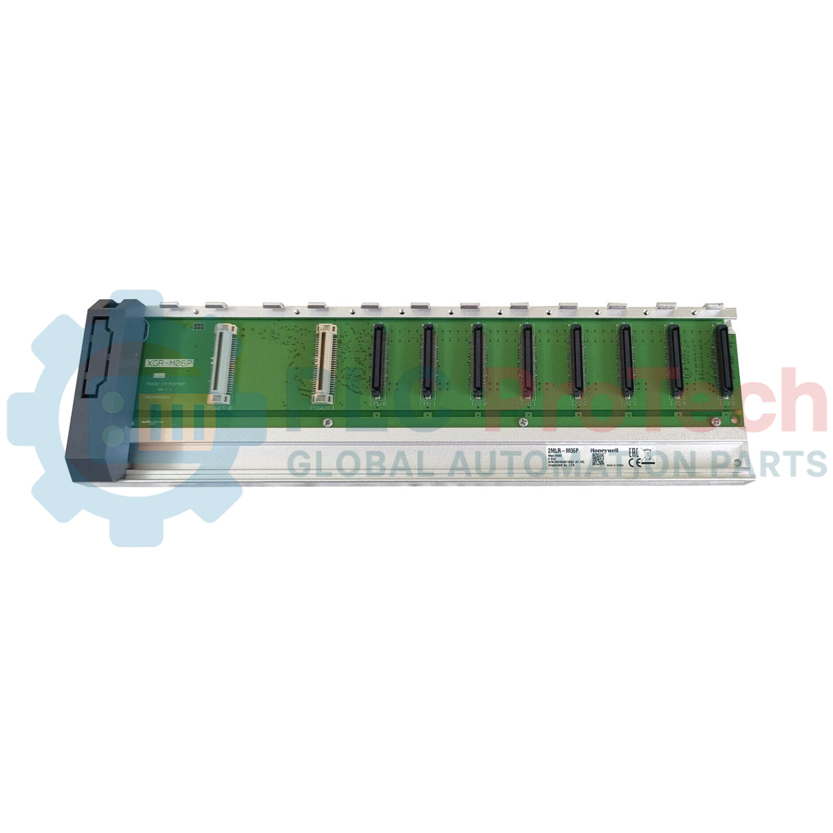
The integration of multi-slot architecture within redundant control topologies is facilitated by the Honeywell 2MLR-M06P base unit, which serves as a dedicated 6-slot main CPU backplane for the MasterLogic programmable controller series. This backplane acts as the physical and electrical foundation, providing high-speed bus communication and power distribution lines to individual processor and expansion modules. Engineered for maximum physical stability, the Honeywell 2MLR-M06P structural chassis ensures reliable alignment of critical pin connectors, preventing communication dropouts under continuous industrial vibration.
Features
- Dedicated 6-slot structural profile allowing simultaneous installation of redundant CPUs and core communication interfaces.
- High-durability backplane bus connectors designed to withstand insertion wear during maintenance cycles.
- Constructed using high-grade polymers meeting the self-extinguishing UL 94V-0 flammability specification.
- Low passive power overhead to maximize overall cabinet energy efficiency.
Applications
- Redundant CPU installations within critical infrastructure control panels.
- Heavy manufacturing process automation requiring dense slot configurations.
- Water treatment facilities, power distribution, and petrochemical processing hubs.
Technical Specifications
| Manufacturer |
Honeywell |
| Model Number |
2MLR-M06P |
| Product Series |
MasterLogic 200R |
| Module Capacity |
6 Slots (Main Base) |
| Compatible Processor Series |
2MLR-CPUH/T, 2MLR-CPUH/F |
| Current Consumption |
211 mA |
| Flammability Rating |
UL 94V-0 |
| Physical Dimensions |
346 mm x 98 mm x 19 mm |
| Net Weight |
0.34 kg |
| Shipping Weight (Calculated) |
1.00 kg |
Alternative Models & Compatibility
The 2MLR-M06P base maintains identical physical dimensions and signal routing properties as corresponding modules within the OEM co-developed LS Electric XGR series (specifically the XGR-M06P). System integrators must verify that firmware configurations (such as Ver 5.1 and higher) are aligned across both redundant CPU units before mounting them to this unified bus.
Application Pitfalls & Engineering Notes
To prevent micro-disconnections along the high-speed CPU synchronization bus, ensure that the mounting panel is completely flat. Mounting the 2MLR-M06P onto an uneven surface can induce physical torsion on the backplane PCB, causing intermittent "Module Pull-Out" alarms or unexpected failovers. Provide sufficient vertical clearance of at least 50 mm above and below the rack to maintain natural convection cooling across installed components.
Commissioning & Wiring Tips
Ensure that the grounding terminal on the power supply module attached to this base is connected directly to a low-impedance earth ground using minimum 2.0 mm² (14 AWG) copper wire. Floating ground potentials on the base plate can introduce high-frequency noise into the system backplane, resulting in checksum errors and degradation of the internal parallel bus communications.
Installation Guidelines
CRITICAL WARNING
Do not install, remove, or modify any modules on the 2MLR-M06P base plate while the system is energized. Failure to completely de-energize the main rack power supply can generate severe transient electrical arcs, permanently damaging the high-speed bus transceivers inside the backplane and any mounted CPU or expansion modules.
1
Position the empty base plate against a clean, flat mounting panel inside the enclosure and align it with the pre-drilled M4 tapped screw holes.
2
Securely tighten the mounting screws across all specified anchoring points to guarantee proper grounding and prevent mechanical flexure.
3
Verify that all backplane slot connectors are completely free of dust and debris before sliding and locking the CPU and functional modules into place.