Description
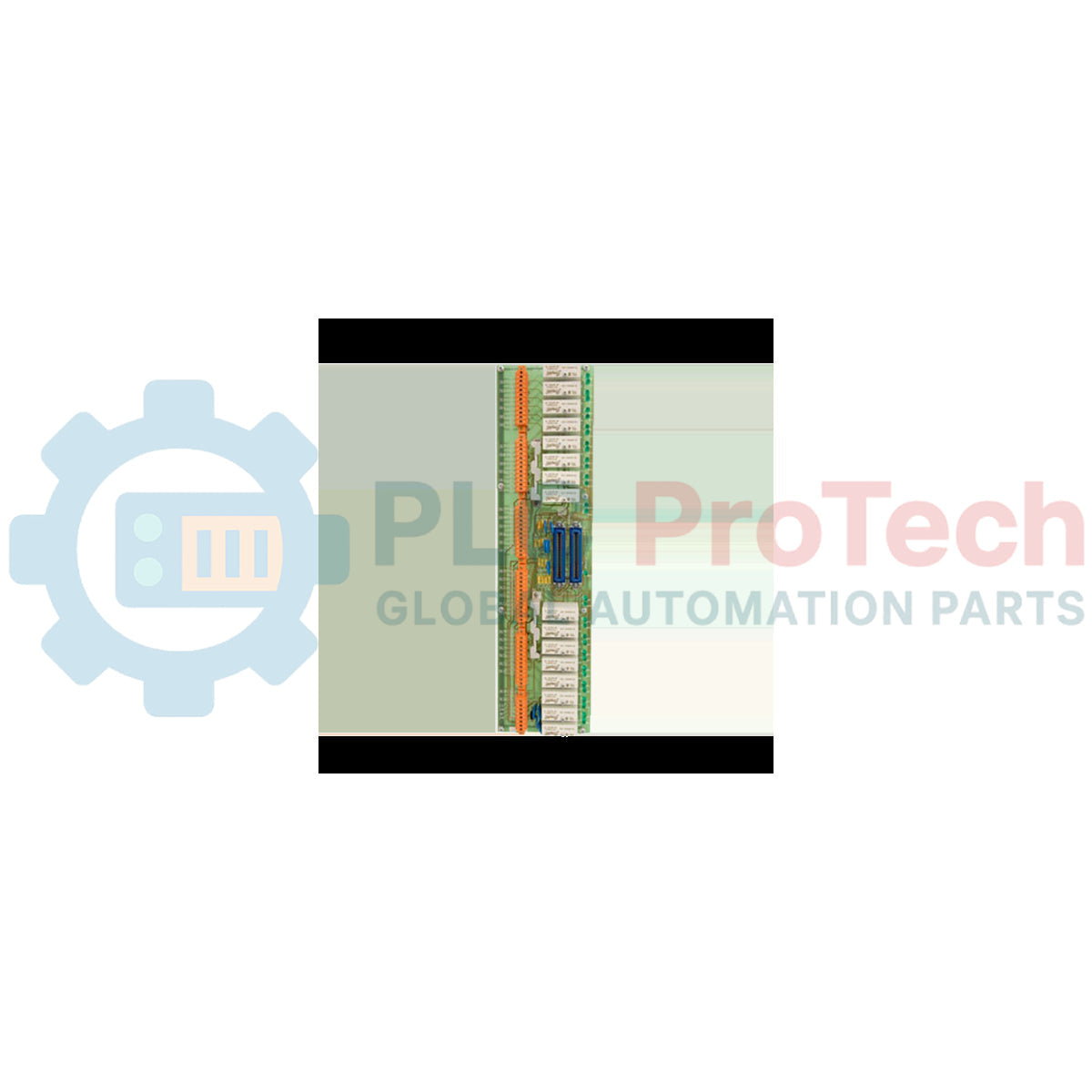
Interfacing directly with field-level contact sensors, the Honeywell 51304441-100 MU-TDID12 serves as a highly reliable 32-channel Digital Input Field Termination Assembly (FTA) within the TDC 3000 and Experion TPS control architectures. This industrial board assembly processes field discrete signals, routing clean status inputs to the system's Digital Input Input/Output Processors (DI IOP). Engineered for continuous operation in demanding process industries, it provides structured termination for complex dry contact loops and active 24 VDC sensing signals.
Features
-
High-Density Architecture: Supports up to 32 individual digital input channels on a single physical footprint.
-
Dual Connection Interfaces: Equipped with 2 onboard FTA ports (50-pin connectors) to allow primary/redundant routing back to the system's IOP cards.
-
Flexible Signal Interface: Designed for standard 24 VDC nominal field interrogation systems.
-
Rugged PCB Board Assembly: Optimized traces and industrial conformal coatings shield board logic from atmospheric contaminants.
-
Industrial Channel Form Factor: Designed to snap quickly into standard industrial FTA mounting channels for neat cabinet layout.
Applications
- Continuous process safety monitoring and limit-switch state tracking.
- Marshalling cabinets in petrochemical, chemical processing, and refining plants.
- Integrating dry auxiliary contacts from MCCs (Motor Control Centers) and local control panels.
- High-density digital signal centralization in legacy TDC 3000 upgrade architectures.
Technical Specifications
| Manufacturer |
Honeywell |
| Model / Article Number |
51304441-100 |
| Commercial Designation |
MU-TDID12 |
| Module Type |
Digital Input Field Termination Assembly (FTA) |
| Input Channel Count |
32 Channels |
| Nominal System Voltage |
24 VDC |
| I/O Ports |
2 x 50-Pin System Connectors |
| Mounting Configuration |
Standard Honeywell FTA Channel Mounting |
| Operating Temperature |
0 to 60 degC |
| Relative Humidity |
5% to 95% RH (non-condensing) |
| Shipping Weight (Calculated) |
2.50 kg |
| Package Dimensions (Calculated) |
310 x 140 x 85 mm |
Connections and Interfaces
| Connector / Terminal Block |
Function / Circuit Assignment |
| System Port 1 (50-Pin) |
Primary interface cable connection to Digital Input IOP |
| System Port 2 (50-Pin) |
Redundant / secondary interface connection for high-availability setups |
| Terminal Strip TB1 (Channels 1-16) |
Field input terminals for channels 1 through 16 (Signal and Return) |
| Terminal Strip TB2 (Channels 17-32) |
Field input terminals for channels 17 through 32 (Signal and Return) |
Empirical Engineering Insights
Alternative Models & Compatibility
The MU-TDID12 belongs to the legacy TDC 3000 I/O line, sharing functional profiles with similar 24 VDC termination boards. Always verify if the matching DI IOP is configured for standard active sensing or passive dry contact loops. Ensure that systemic cable lengths (50-pin ribbon or round cabling) do not exceed Honeywell's maximum system bus limit to prevent signal attenuation.
Application Pitfalls & Engineering Notes
When utilizing this assembly in high-density configurations, avoid running field input lines parallel to high-voltage AC cables in marshalling channels. Excessive electromagnetic noise can lead to false transitions on the sensitive 24 VDC inputs. To ensure overall module health, verify that cabinet thermal dynamics do not exceed 60 degC, as concentrated heat inside closed cabinets shortens the lifespan of the board's passive components.
Commissioning & Wiring Tips
Prior to firing up the control loop, perform a loop impedance test across the field contacts. Excessively high field line resistance (above standard thresholds) can prevent the digital input channel from registering a closed-circuit state. Using clean shielded twisted pairs for external loops is recommended to minimize cross-talk and potential earth-ground referencing issues.
Installation Guidelines
CRITICAL WARNING: De-energize all field instrumentation and internal cabinet power distribution systems before physical installation, removal, or maintenance. Failure to isolate voltage sources can lead to severe system shock, card destruction, or unexpected process shutdown.
1
Mount the MU-TDID12 FTA securely onto the dedicated horizontal or vertical cabinet mounting channel, verifying that all mounting clips are engaged.
2
Plug the dual 50-pin system interface cables firmly into System Port 1 and Port 2, ensuring the retaining clips are locked.
3
Terminate the 32 discrete field input pairs on terminal blocks TB1 and TB2 according to the system P&ID layout maps.
4
Verify the shield grounds are properly referenced to the cabinet ground bus bar before applying 24 VDC interrogation power.