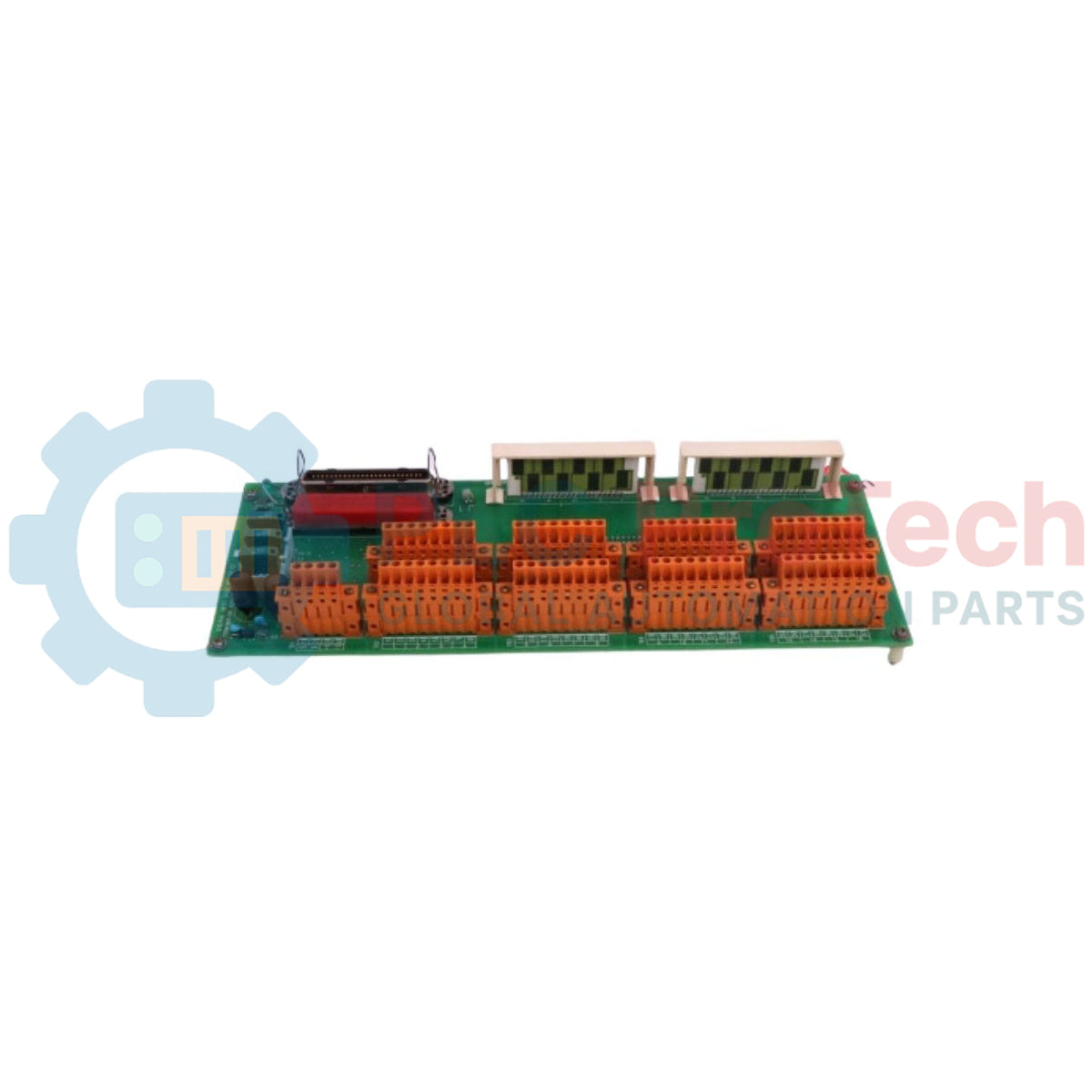
Description
Designed to expand internal power distribution networks within high-integrity industrial safety architectures, the Honeywell FS-PDB-IOX05 acts as a dedicated power distribution board extension. This unit routes auxiliary electrical lines and stabilizes feed paths directly to input/output structures inside Honeywell Safety Manager environments. By utilizing robust pin headers and standard DIN-rail mounting configurations, the module ensures secure mechanical and electrical connections that prevent accidental signal or power interruptions in critical control panels.
Features
- Dedicated safety system extension designed specifically for Honeywell Safety Manager architectures.
- High-reliability action pin header connection points for solid signal path contact.
- Standardized dual DIN-rail compatibility matching standard industrial panel configurations.
- Passive bus structure minimizing active component failures within critical power lines.
Applications
- Emergency Shutdown Systems (ESD) requiring redundant internal power routing.
- Fire and Gas (F&G) safety control loop distribution networks.
- High-integrity process safety installations (SIL 2 / SIL 3 environments).
Technical Specifications
| Specification Parameter |
Verified Technical Value |
| Manufacturer |
Honeywell |
| Model Number |
FS-PDB-IOX05 |
| Module Type |
Power Distribution Board Extension |
| Mounting Compatibility |
DIN EN Rails TS32 / TS35 x 7.5 |
| Required Rail Length |
171 mm (6.73 in) |
| Module Dimensions (W x H x D) |
170 x 70 x 46 mm |
| Compliance & Approvals |
CE, UL, TUV, CSA |
| Shipping Weight (Calculated) |
2.0 kg |
Connections and Interfaces
| Interface Connection |
Pin Configuration / Design |
| 5V-x Port |
4-position, action pin header |
| WdPx Port |
8-pole, male pin header |
Empirical Engineering Insights
Alternative Models & Compatibility
The FS-PDB-IOX05 is designed exclusively for Honeywell Safety Manager IO integration. It cannot be mixed with older generation FSC systems unless matching backplane adaptations and safety approvals are fully re-evaluated at the system level. When replacing legacy distribution blocks, verify the revision status of the internal ribbon and connection headers.
Application Pitfalls & Engineering Notes
Due to the passive nature of this board, it does not include on-board active current limiting elements. Over-current conditions originating downstream will directly impact the upstream safety supply modules if external fusing protocols are not followed. Verify that panel thermal management allows for heat dissipation when installed inside high-density enclosures.
Commissioning & Wiring Tips
When connecting the action-pin connectors (5V-x), apply insertion force straight onto the header. Angular insertion risks bending the connection pins, which compromises mechanical integrity and leads to high-resistance contacts that trigger systemic diagnostic fault states on safety controller cards.
Installation Guidelines
CRITICAL WARNING: Ensure all main and auxiliary power feeds are fully disconnected and locked out before attempting installation, replacement, or wiring of this module. Failure to isolate power paths can result in unpredictable controller behavior, system trips, or hazardous electrical contact.
1
Mount the board onto clean, unpainted TS32 or TS35 DIN rails, ensuring a minimum linear rail length allowance of 171 mm is maintained for mechanical stability.
2
Carefully align and mate the 4-position action-pin 5V-x connection header to the system power bus lines without applying offset lateral pressure.
3
Connect the 8-pole WdPx pin header using matching Honeywell safety-approved wiring assemblies, securing the routing channels to avoid cable tension.
4
Perform low-impedance grounding and continuity checks across the assembly before re-energizing the main safety cabinet.