Description
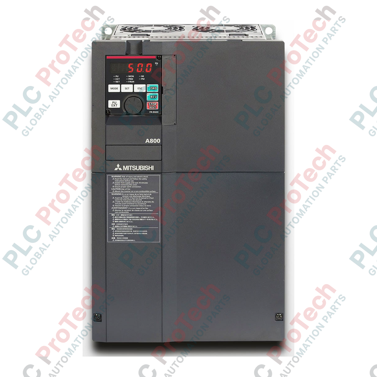
Engineered for high-performance motor control in demanding industrial environments, the Mitsubishi Electric FR-A840-00620-2-60 variable frequency drive delivers exceptional vector control accuracy within the FR-A800 Series architecture. This three-phase inverter is optimized for constant torque applications, providing reliable speed and torque regulation for heavy-duty machinery. With its integrated 6K-step PLC and advanced safety functionalities, the drive simplifies system architecture by eliminating the need for external controllers in localized automation loops.
Features
-
Real Sensorless Vector (RSV) Control: Achieves high-precision speed and torque control up to 400 Hz without requiring a dedicated encoder feedback loop.
-
Integrated Safety Architecture: Built-in compliance with SIL2 and PLd safety standards ensures safe torque-off (STO) functionality directly at the drive level.
-
Embedded Automation Logic: Built-in Mitsubishi L-Series PLC functionality allows for customized control programming up to 6,000 steps.
-
Energy Optimization: Optimum Excitation Control technology continuously tunes the motor flux to minimize losses, yielding up to an additional 12% energy savings over standard V/f control.
-
Diagnostic Maintenance: Internal thermal sensors and component life diagnostics track the degradation of main circuit capacitors, cooling fans, and inrush currents.
Applications
-
Winding and Tensioning Systems: Direct tension control and dancer feedback loops for paper, film, and wire lines.
-
Cranes and Hoists: Smooth brake sequence control and high-torque generation at zero speed for lifting mechanisms.
-
Machine Tool Spindles: High-speed orientation and rapid acceleration/deceleration performance under variable loads.
-
Heavy Conveyors: Master-slave torque sharing configurations for multi-drive bulk material handling systems.
Technical Specifications Table
| Parameter |
Specification Value |
| Manufacturer |
Mitsubishi Electric |
| Model Number |
FR-A840-00620-2-60 |
| Series |
FR-A800 |
| Input Voltage Rating |
3-Phase 380 to 500V AC (50Hz / 60Hz) |
| Output Capacity (ND / Heavy Duty) |
22 kW |
| Rated Output Current (ND) |
44 A |
| Control Modes |
V/F, Advanced Magnetic Flux Vector, Real Sensorless Vector, Closed-Loop Vector |
| IP Protection Rating |
IP20 (Open Type) |
| Cooling Method |
Forced Air Cooling |
| Brake Chopper |
Built-in (requires external resistor for high duty cycles) |
| Shipping Weight (Calculated) |
16.0 kg |
| Physical Dimensions (H x W x D) |
400 mm x 250 mm x 190 mm |
Connections and Interfaces
| Terminal Designation |
Function / Assignment |
| R/L1, S/L2, T/L3 |
Three-phase AC power input connections |
| U, V, W |
Three-phase AC output connections to motor |
| P/+, PR |
External braking resistor connection terminals |
| P/+, N/- |
Direct DC bus connection link for common-bus sharing |
| S1, S2, SC |
Dual-channel Safety stop input terminals (STO) |
Empirical Engineering Insights
Alternative Models & Compatibility
The FR-A840-00620-2-60 is fully backwards compatible with the legacy FR-A740-00620 series parameters. By utilizing the FR-Configurator 2 software suite, users can migrate parameters without manual re-entry. Note, however, that physical footprint and terminal block locations differ slightly; ensure mounting panels accommodate the depth variance of 190 mm.
Application Pitfalls & Engineering Notes
When deploying this drive in constant-torque configurations at low frequencies (below 6 Hz), standard self-cooled motors will experience high heat generation due to reduced fan speed. In these scenarios, a motor with an independent cooling fan (forced ventilation) is required. Ensure the drive enclosure maintains a 100 mm top and bottom clearance for unrestricted heat sink airflow.
Commissioning & Wiring Tips
For reliable RS-485 or SSCNet communication, control wiring must use twisted-pair shielded cables separate from the power cables. Keep the control wiring separated from the main circuit wiring by at least 10 cm to prevent high-frequency electromagnetic interference. Connect the shield braid directly to the ground plate rather than using a pigtail connection.
Installation Guidelines
CRITICAL WARNING
Hazardous voltages remain present in the internal DC bus capacitors even after mains power is disconnected. Wait a minimum of 10 minutes after complete de-energization, and verify with a multimeter that the DC bus voltage (terminals P/+ to N/-) has discharged below 50VDC before initiating physical contact with terminal wiring.
1
Mount the inverter vertically on a flat, non-flammable vertical wall using M6 size mounting bolts. Avoid tilted installations to ensure optimal thermal chimney-effect dissipation.
2
Connect the protective earth (PE) ground wire to the designated ground terminal before routing primary three-phase lines to the R/L1, S/L2, and T/L3 terminals.
3
Ensure the terminal cover is securely locked back into place before switching on the primary input breaker to perform initial parameters verification.