Description
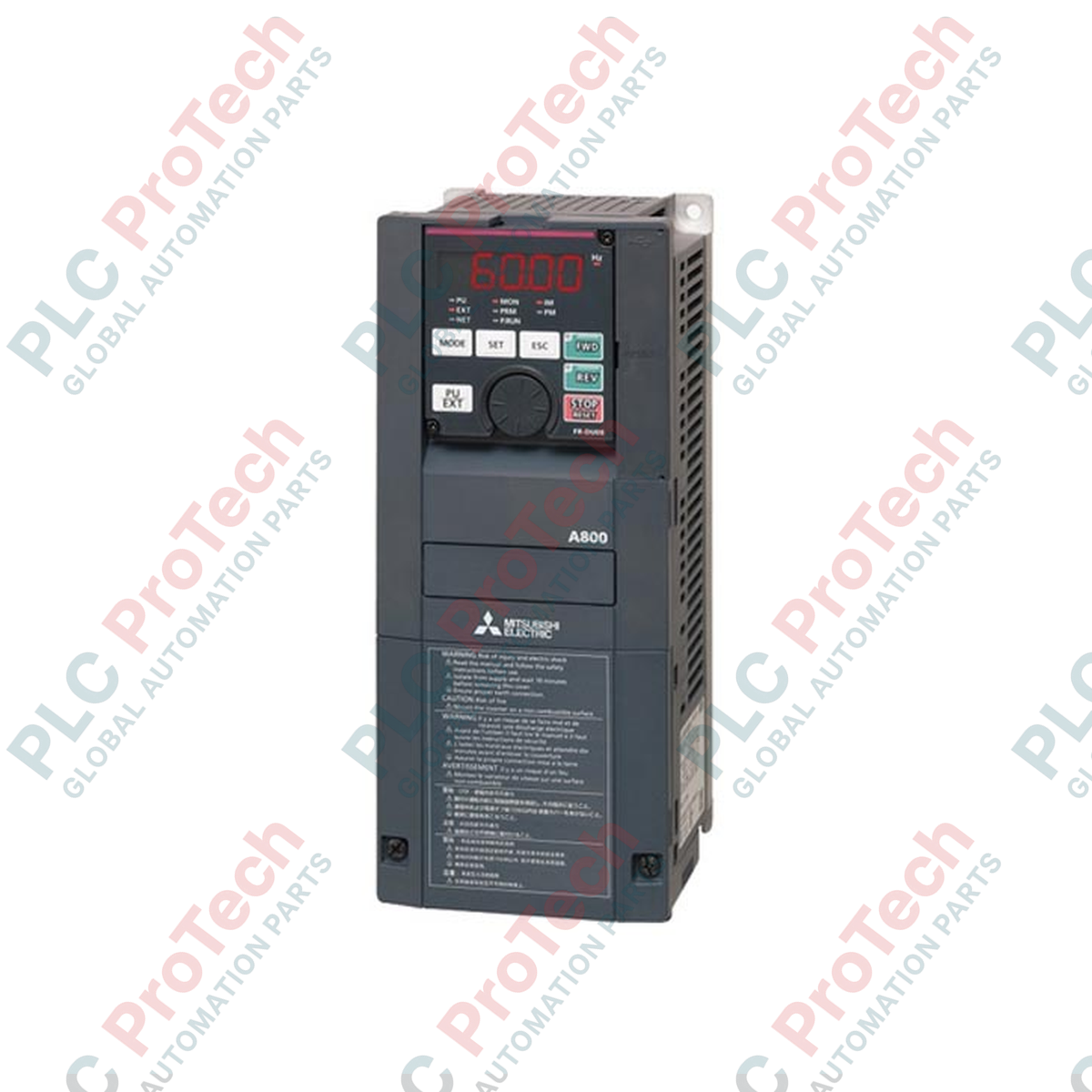
Designed for high-performance industrial motor control, the FR-A840-1.5K-1 by Mitsubishi Electric operates as a premium variable frequency drive within the FR-A800 series. This high-capacity inverter delivers exceptional speed and torque control for 1.5 kW three-phase motors, relying on advanced real-time sensorless vector control algorithms. Built to withstand demanding manufacturing environments, the unit integrates standard serial communication architectures, high-efficiency cooling, and robust overcurrent protection to ensure continuous field operation and minimize plant downtime.
Features
- Real-time sensorless vector control capabilities for ultra-precise speed and torque response.
- Built-in RS-485, RS-422, and RS-232 serial communication interfaces supporting Modbus RTU protocols.
- Dual overload rating tolerance designed for versatile normal duty (ND) and light duty (LD) load characteristics.
- Embedded safety-related stop function conforming to international industrial standards.
- Integrated EMC filter to minimize electromagnetic noise and safeguard adjacent control instrumentation.
Applications
- Material handling conveyor lines requiring precise acceleration and deceleration profiles.
- Centrifugal pump systems and industrial fan setups utilizing variable torque optimization.
- Extrusion lines and continuous mixers within chemical and plastics processing facilities.
- Machine tool spindles requiring stable speed holding under variable mechanical loads.
Technical Specifications
| Parameter |
Value |
| Manufacturer |
Mitsubishi Electric |
| Model Reference |
FR-A840-1.5K-1 |
| Series Name |
FR-A800 |
| Input Voltage Class |
Three-phase 400 V (380 to 500 VAC, 50/60 Hz) |
| Applicable Motor Capacity |
1.5 kW |
| Output Rated Current |
4.0 A |
| Output Rated Capacity |
3.0 kVA |
| Communication Interfaces |
RS-232, RS-422, RS-485 (Mitsubishi / Modbus RTU) |
| Standards & Approvals |
CE, UL, cUL, RoHS |
| Enclosure Rating |
IP20 |
| Physical Dimensions (H x W x D) |
260 mm x 150 mm x 140 mm |
| Shipping Weight (Calculated) |
4.5 kg |
Connections and Interfaces
| Terminal Designation |
Circuit / Function Assignment |
| R/L1, S/L2, T/L3 |
Main Three-Phase AC Power Input Connection |
| U, V, W |
Three-Phase Variable Frequency Output to Motor |
| P/+, PR |
Braking Resistor Connection Terminals |
| STF / STR |
Forward Run Start / Reverse Run Start Digital Inputs |
| SD |
Common Terminal for Digital Inputs and 24 VDC Power source |
| 2, 4, 5 |
Analog Frequency Setting Inputs (Voltage / Current) & Common Ground |
Alternative Models & Compatibility
The FR-A840-1.5K-1 serves as the direct technological replacement for legacy FR-A740-1.5K series drive models. While the footprint and control terminals line up similarly, please note that parameter structures have expanded. When utilizing FR Configurator2 software to import existing parameter files from A700 series models, a careful verification of acceleration-deceleration curve parameters and motor tuning maps must be performed to ensure smooth commissioning.
Application Pitfalls & Engineering Notes
During integration inside IP54 enclosed control panels, local heat dissipation must be handled correctly. The drive requires a minimum space clear-zone of 50 mm above and below the chassis for unimpeded natural airflow. In applications operating continuously at low speeds under high-torque demand, the integrated motor fan will lose efficiency. Always implement an external forced cooling fan on the motor or utilize inverter-duty rated motors to prevent winding thermal trips (E.THT faults).
Commissioning & Wiring Tips
Ensure that Parameter 79 (Operation Mode Selection) is explicitly set to match your system master. For example, setting Pr.79 to "2" locks control logic exclusively to the external terminals, bypassing the PU keypad. For RS-485 serial communication daisy chains, apply a terminating resistor on the final physical node and run standard double-shielded twisted pair (STP) control cables. The shield must be terminated strictly at a single point (PE ground at the cabinet entry) to prevent destructive ground loops.
Installation Guidelines
CRITICAL WARNING
Isolate all main power lines prior to physical cabinet mounting or control terminal wiring. Once input power is switched off, wait a minimum of 10 minutes for the internal DC bus capacitors to fully discharge. Always measure the DC bus voltage across terminals P/+ and N/- using a calibrated digital multimeter to verify the potential is below 50 VDC before initiating touch-sensitive electrical tasks.
1
Securely mount the variable speed drive on a rigid, vibration-resistant vertical panel backplate using appropriate M5 bolts.
2
Connect the physical PE protective ground terminal directly to the central cabinet earth bar before wiring power supply lines.
3
Terminate the three-phase power lines at R/L1, S/L2, and T/L3, ensuring correct phase configuration, and route the motor outputs from U, V, and W.
4
Secure control signal wiring away from the high-voltage power lines inside separate wire ducting lanes to prevent inductive cross-talk.