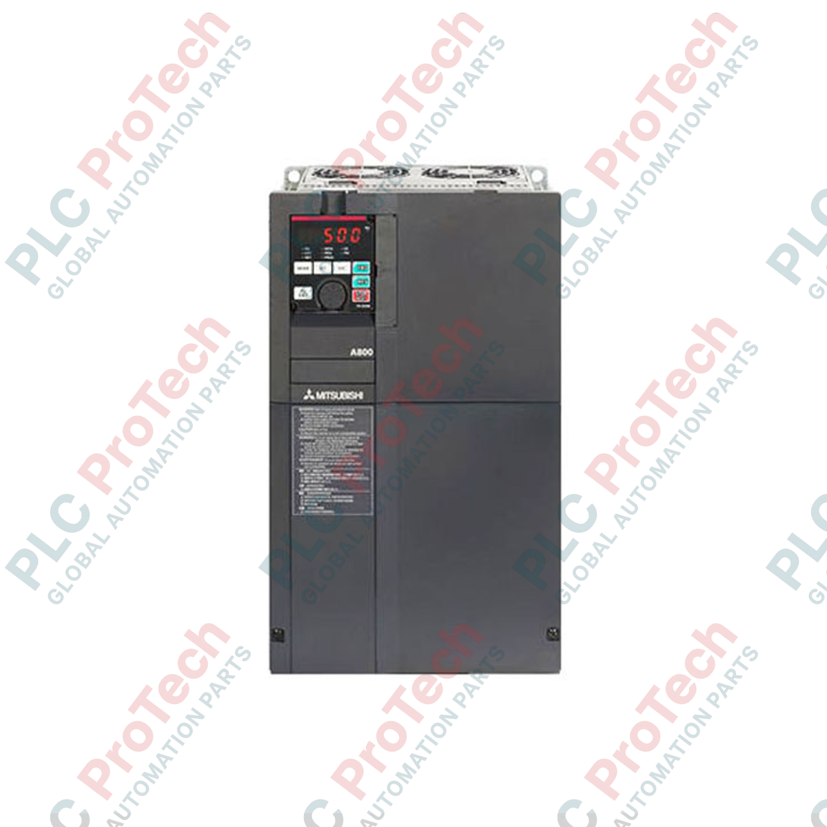
Description
Engineered for high-demand heavy industrial applications, the Mitsubishi Electric FR-A840-75K-1 variable frequency drive delivers precise speed and torque control for motors up to 75 kW. Incorporating advanced vector control algorithm technologies, this three-phase 400V class inverter maximizes operational uptime and system efficiency in demanding processing environments. The unit features a dedicated FM terminal configured for high-speed pulse train output, enabling real-time feedback and seamless integration into higher-level DCS and PLC architectures.
Features
-
Real Sensorless Vector Control: Achieves high-accuracy torque control and exceptional dynamic response without requiring a physical speed encoder.
-
Built-in RS-485 Communication: Supports Modbus-RTU and Mitsubishi standard protocols directly via the RJ-45 interface, with expansion options for CC-Link, Profibus-DP, EtherCAT, and PROFINET.
-
Enhanced Terminal FM Interface: Provides high-speed pulse train output (up to 55 kHz) for monitoring critical operating parameters such as output frequency or motor speed.
-
High Overload Capacity: Designed to withstand heavy-duty industrial cycles with dual ratings for Normal Duty (ND) and Light Duty (LD) operational demands.
-
Built-in PLC Functionality: Allows custom logic sequences to be programmed directly within the drive, reducing the need for external control components.
Applications
- Heavy-duty industrial extraction fans and high-volume ventilation blowers.
- Multi-stage centrifugal pumps and water treatment processing systems.
- Heavy-material conveyors, overhead cranes, and material handling gantries.
- Compressors, extruders, and industrial mixing machinery.
Technical Specifications Table
| Specification Parameter |
Value / Rating |
| Manufacturer |
Mitsubishi Electric |
| Model Number |
FR-A840-75K-1 |
| Applicable Motor Capacity |
75 kW (Heavy Duty) / 90 kW (Normal Duty) |
| Input Voltage Class |
Three-Phase 380 to 500 V AC (50/60 Hz) |
| Rated Output Current |
144 A (Heavy Duty) / 180 A (Normal Duty) |
| Output Capacity |
110 kVA |
| Control Method |
V/F Control, Advanced Magnetic Flux Vector Control, Real Sensorless Vector Control |
| Monitor Output Terminal |
Terminal FM (Pulse Train Type) |
| Communication Protocols |
RS-422, RS-485 (Built-in Modbus RTU) |
| Protective Rating |
IP00 (Open Type) |
| Operating Temperature |
-10 degC to +50 degC (Non-freezing) |
| Compliance & Certifications |
CE, UL, cUL, RoHS compliant |
| Country of Origin |
Japan |
| Shipping Weight (Calculated) |
53.0 kg (116.8 lbs) |
| Physical Dimensions (W x H x D) |
465 mm x 595 mm x 300 mm |
Empirical Engineering Insights
Alternative Models & Compatibility
The FR-A840-75K-1 serves as the direct replacement for the legacy FR-A740-75K model series. While the footprint and control terminal layouts are largely identical, parameter migration must be handled carefully. When upgrading, parameters should be exported via FR Configurator2 software to ensure custom logic programs and PID loop configurations translate correctly. Note that the "-1" suffix designates the unit equipped with the FM terminal interface (pulse output) as opposed to the "-2" suffix which features an AM terminal (analog voltage output).
Application Pitfalls & Engineering Notes
Operating a 75 kW high-capacity drive generates substantial thermal loads, approximately 1850 Watts of heat dissipation at full capacity. Enclosing this unit within sealed IP54 panels requires forced mechanical cooling to prevent the internal heatsink from exceeding 50 degC, which triggers an overtemperature warning (E.THT). Additionally, installing an external DC link reactor (FR-HEL) is highly recommended to protect the rectifier bridge from input line surges and reduce high-frequency harmonic feedback into the distribution transformer.
Commissioning & Wiring Tips
When routing cables for the FM pulse output terminal, use braided, shielded twisted-pair (STP) wiring with a minimum wire cross-section of 0.75 mm2. Keep control cables physically isolated from the output motor phases (U, V, W) by a distance of at least 30 cm to prevent EMI noise injection, which can distort pulse output readings. If the drive displays an E.UVT (Undervoltage) fault during ramp-up, verify that the input voltage supply does not sag below 323 V AC under transient loading conditions.
Installation Guidelines
CRITICAL WARNING: HIGH VOLTAGE RISK
Isolate all primary feed circuits before executing installation. Wait a minimum of 10 minutes post-power-down to allow internal DC bus capacitors to discharge below safety thresholds. Confirm that the DC bus voltage across terminals P/+ and N/- is measured at 0 V with a rated digital multimeter before initiating terminal modifications.
1
Mount the drive vertically on a flat, non-flammable vertical backplate to optimize convection cooling currents across the heatsink assembly.
2
Connect the mains power cabling to terminals R/L1, S/L2, and T/L3. Connect the output motor cabling to terminals U, V, and W. Ensure all ground lugs are connected to a low-impedance facility earth bus.
3
Perform a dry run setup with the motor disconnected. Set Parameter 9 (Motor Rated Current) and Parameter 71 (Applied Motor Selection) via the onboard PU display before running an autotuning sequence.