Description
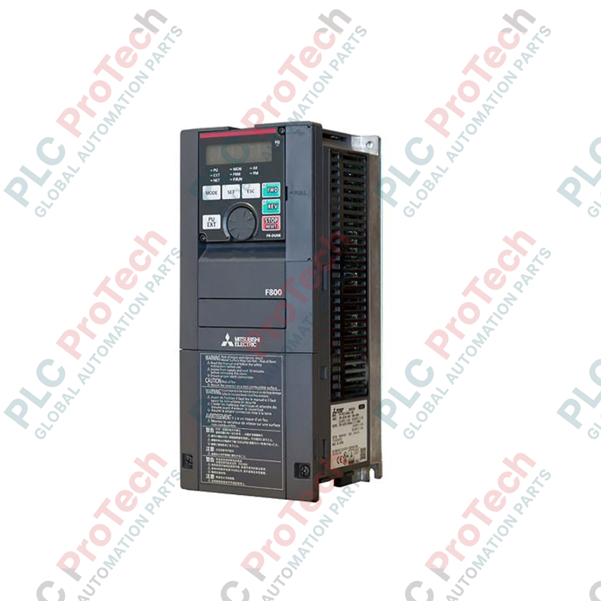
Optimizing energy consumption in industrial pump and fan applications, the Mitsubishi Electric FR-F840-02600-2-60 represents a heavy-duty, high-performance FR-F800 series variable frequency drive engineered for fluid-flow control. This advanced inverter has a rated output current of 260 A and is designed to control three-phase motors up to 132 kW. With its specialized circuit board coating and unplated conductors (designated by the "60" configuration suffix), this drive offers improved environmental resistance in demanding industrial atmospheres. The unit incorporates intelligent energy-saving algorithms, such as Optimum Excitation Control, to maximize motor efficiency under fluctuating loads while maintaining an open-type (IP00) protective structure ideal for control cabinet integration.
Features
-
Enhanced Environmental Protection: The "60" suffix indicates conformal-coated circuit boards with unplated conductors, safeguarding electronics from airborne contaminants.
-
Optimized Pump and Fan Control: Designed specifically for variable torque loads, utilizing advanced excitation control to reduce energy usage.
-
High Current Capacity: Capable of delivering a rated continuous current of 260 A to heavy-duty industrial motors.
-
Forced Air Cooling: High-volume integrated cooling fans prevent thermal buildup, maintaining performance within high-density control panels.
-
Robust Input Tolerance: Allows input voltage fluctuations ranging from 323 V to 550 V AC to prevent nuisance trips during grid instability.
Applications
- Water treatment facilities and high-volume sewage pumping stations.
- Commercial HVAC air handling units, industrial exhaust blowers, and supply fans.
- Secondary cooling tower fan operations and circulation pump loops in chemical plants.
- Secondary combustion air supply systems in heavy industrial boilers.
Technical Specifications
| Parameter |
Value |
| Manufacturer |
Mitsubishi Electric |
| Model Code |
FR-F840-02600-2-60 |
| Series |
FR-F800 |
| Applicable Motor Capacity |
132 kW |
| Rated Output Capacity |
198 kVA |
| Rated Output Current |
260 A |
| Output Voltage |
Three-phase 380 to 500 V AC |
| Rated Input AC Voltage/Frequency |
Three-phase 380 to 500 V AC, 50 Hz / 60 Hz |
| Permissible AC Voltage Fluctuation |
323 to 550 V AC |
| Permissible Frequency Fluctuation |
±5% |
| Power Supply Capacity |
248 kVA |
| Protective Structure (JEM1030) |
Open type (IP00) |
| Cooling System |
Forced air cooling |
| Net Weight |
55 kg |
| Shipping Weight |
60 kg |
Empirical Engineering Insights
Alternative Models & Compatibility
When migrating legacy systems from the FR-F740 series to the FR-F840-02600-2-60, verify the mechanical footprint as mounting points and depths differ slightly in the 132 kW range. The "2" in the model designation indicates standard European specifications (filter/EMC options), while the "60" suffix indicates circuit board coating, making it directly compatible with harsh environment requirements where non-coated legacy variants failed prematurely.
Application Pitfalls & Engineering Notes
Because this VFD is classified under an open-type IP00 protective structure, it must be installed inside a dedicated industrial electrical enclosure. At 132 kW, heat dissipation is considerable. Ensure the enclosure's thermal management system can exhaust the heat generated by a drive operating at 260 A output. Do not restrict the forced-air intake or exhaust areas on the frame of the inverter.
Commissioning & Wiring Tips
To prevent electromagnetic interference (EMI) with analog signal lines, route high-power output cabling separately from control wiring. Always ensure the ground loop configuration returns directly to the VFD's primary grounding busbar. When wiring the main circuit terminals, use correct torque specifications to prevent terminal overheating due to contact resistance.
Installation Guidelines
CRITICAL WARNING
Hazard of electrical shock, burn, and explosion. Disconnect and lock out all input power lines before attempting terminal block connections or maintenance. After de-energizing, wait a minimum of 10 minutes to allow the high-voltage DC bus capacitors to discharge to safe levels. Verify zero voltage on the DC terminals before proceeding.
1
Mount the IP00 inverter vertically on a flat, non-flammable vertical wall inside a dust-free and ventilated control cabinet.
2
Connect the three-phase power supply lines to terminals R/L1, S/L2, and T/L3. Connect the motor leads to U, V, and W terminals. Ensure correct phase rotation.
3
Securely connect the grounding wire to the main protective earth terminal. Do not daisy-chain the ground line with other devices.