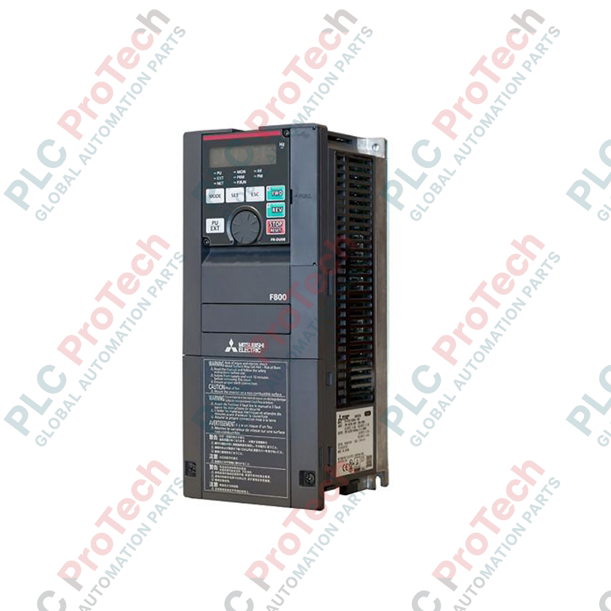
Description
Optimizing flow control in heavy-duty pump and fan installations, the Mitsubishi Electric FR-F840-03250-2-60 functions as a heavy-capacity variable frequency drive from the FR-F800 series. This industrial inverter is engineered specifically for fan, pump, and compressor control, delivering high-efficiency operation through intelligent energy-saving algorithms. Incorporating advanced excitation control, it continuously monitors load demand to optimize torque and reduce power consumption in real time.
Features
-
Advanced Optimum Excitation Control: Automatically balances motor magnetic flux to achieve high energy efficiency even under changing load conditions.
-
Dual Overload Rating: Supports Super Light Duty (SLD) and Light Duty (LD) operational configurations to match specific load profiles.
-
Multi-Pump Control: Built-in advanced PID and multi-pump control algorithms allow coordinated operation of multiple auxiliary pumps.
-
Integrated Safety Function: Features functional safety inputs compliant with SIL 2 / PL d safety standards.
-
Onboard PLC Functionality: Enables basic logic programming directly within the inverter, reducing the need for external mini-PLCs.
Applications
-
Water and Wastewater: Intake pumps, booster stations, and aeration blower systems.
-
HVAC Systems: Large-scale industrial air handling units (AHUs), cooling towers, and chillers.
-
Factory Automation: Dust collectors, exhaust fans, and municipal ventilation systems.
Technical Specifications
| Parameter |
Specification Value |
| Manufacturer |
Mitsubishi Electric |
| Model Number |
FR-F840-03250-2-60 |
| Series Name |
FR-F800 Series |
| Input Voltage Range |
3-Phase 380 to 500 VAC (50/60 Hz) |
| Rated Output Current (SLD) |
325 A |
| Rated Output Current (LD) |
290 A |
| Control Method |
V/f Control, Advanced Magnetic Flux Vector Control, Optimum Excitation Control |
| Enclosure Protection Rating |
IP00 (Open Type) |
| Operating Ambient Temperature |
-10 to +50 degC (non-freezing, LD rating up to +40 degC without derating) |
| Shipping Weight (Calculated) |
74.0 kg |
Connections and Interfaces
| Terminal Group |
Function Assignment |
| R/L1, S/L2, T/L3 |
3-Phase AC main power input connections. |
| U, V, W |
3-Phase AC motor power output connections. |
| P/+, PR, N/- |
DC link terminals for optional braking units or shared DC bus configurations. |
| Control Terminals |
Analog inputs (voltage/current), multi-function digital inputs, safety stop (S1/S2/SIC), and relay outputs. |
Alternative Models & Compatibility
The unit acts as a direct modern replacement for the legacy FR-F740-03250 series. When replacing older F700 series models, parameter configuration files can be migrated using the FR Configurator2 software suite. Note that physical dimensions and mounting bolt patterns may differ slightly from the legacy series; ensure layout spacing in enclosed cabinets allows for the ventilation clearances required by the FR-F800 design.
Application Pitfalls & Engineering Notes
This large-capacity inverter exhibits significant thermal dissipation requirements during peak loads. Ensure your electrical enclosure has active ventilation capable of moving hot air away from the drive heat sinks, especially if operating continuously in ambient environments above 40 degC. For installations exceeding 1000 meters above sea level, apply a current derating factor of 1% per 100 meters up to a maximum altitude of 2500 meters.
Commissioning & Wiring Tips
Always ground the drive independently using a Class D grounding connection with a low impedance path. Ground currents generated by high-frequency PWM switching can interfere with sensitive near-field analog signals. It is highly recommended to run encoder, transducer, and control loops in separate, shielded conduits isolated from the main U/V/W motor output cables by at least 30 cm.
Installation Guidelines
CRITICAL WARNING: HIGH-VOLTAGE RISK
Before beginning any installation, maintenance, or terminal wiring work, completely disconnect the main power source. Wait at least 10 minutes for the internal DC bus capacitors to discharge safely. Verify that the charge indicator lamp on the front cover is completely off and measure the voltage across terminals P/+ and N/- to confirm it is below 30 VDC.
1
Mount the inverter vertically onto a flat, non-flammable vertical surface (such as a metal backplate) to guarantee optimal convective airflow across the rear-mounted heat sinks.
2
Connect structural grounds to the designated ground terminals. Securely connect the R/L1, S/L2, and T/L3 incoming power lines and the U, V, and W motor cables using the specified M8/M10 terminal bolt torque specs.
3
Wire the external safety inputs to the dual-channel S1/S2 safety terminals if emergency stop integration is required, ensuring the jumper is removed if using an external safety relay.